
System and method for providing transparent LAN services

a technology of transparent lan and services, applied in the field of communication networks, can solve the problems of high cost of limited use of foregoing approaches, and inability to easily scale up point-to-point private line circuit solutions, etc., and achieve the effect of reducing bandwidth efficiency

Inactive Publication Date: 2009-03-19
ADTRAN
View PDF60 Cites 27 Cited by
  • Summary
  • Abstract
  • Description
  • Claims
  • Application Information

AI Technical Summary

Benefits of technology

[0010]Pursuant to another aspect of the present invention, bandwidth efficiency is achieved by using native layer two broadcast of multicast MPLS data packet over a fiber optic ring having a Resilient Packet Ring (RPR) topology. Hence, a separate packet need not be sent to each of the nodes. Rather, a single multicast MPLS data packet is sent over the ring. By sending one, rather than several, MPLS data packet over the ring, bandwidth efficiency is achieved.
[0016]The node also maintains an association table that associates the unicast label, or source label, and the source IP address with the source MAC address of the transmitting device. Thus, for future data transmissions to a device having that source MAC address, the node may unicast the data packet by appending the known unicast MPLS label associated with the device having that source address and a ring header, rather than multicasting the data packet, thereby furthering bandwidth efficiency.

Problems solved by technology

In some applications, use of the foregoing approaches is limited in providing network users an efficient, scalable solution.
Thus, the point-to-point private line circuit solution is not easily scalable and for large numbers of locations even larger numbers of point-to-point private line circuits are necessary.
Indeed, for large numbers of locations, a point-to-point private line circuit solution can be expensive due to the cost of establishing and maintaining the various point-to-point private line circuits.
In addition, the point-to-point private line circuit solution is not bandwidth efficient.
That is, unused bandwidth on some of the point-to-point private line circuits is not typically available for routing network traffic traversing other of the point-to-point private line circuits.
The point-to-point private line circuit solution is further inefficient since data packets sent to all locations must be set over each of the multiple point-to-point private line circuits.

Method used


Image

  • System and method for providing transparent LAN services
  • System and method for providing transparent LAN services
  • System and method for providing transparent LAN services

Examples


Embodiment Construction

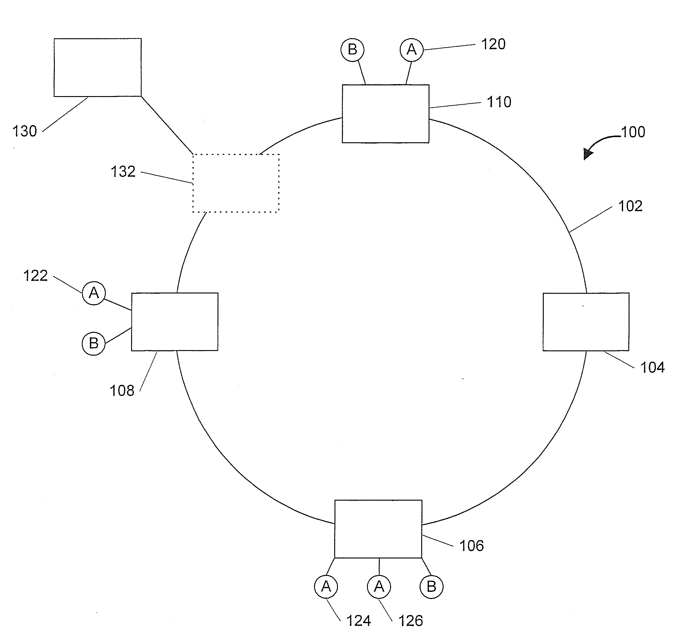
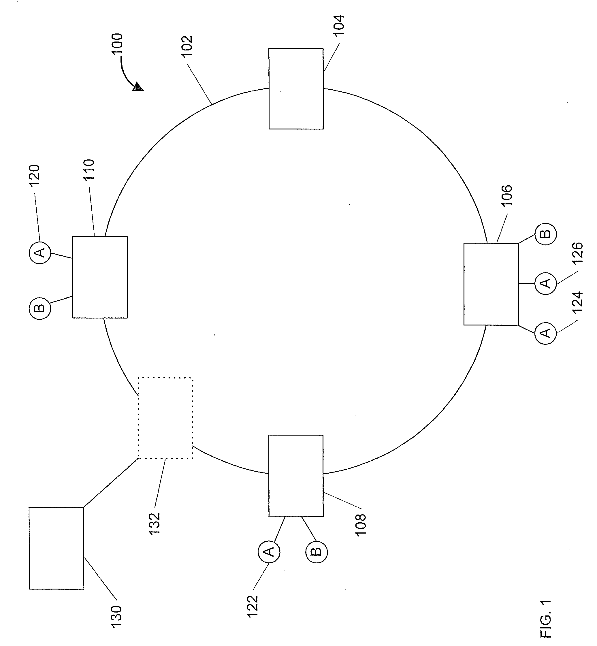
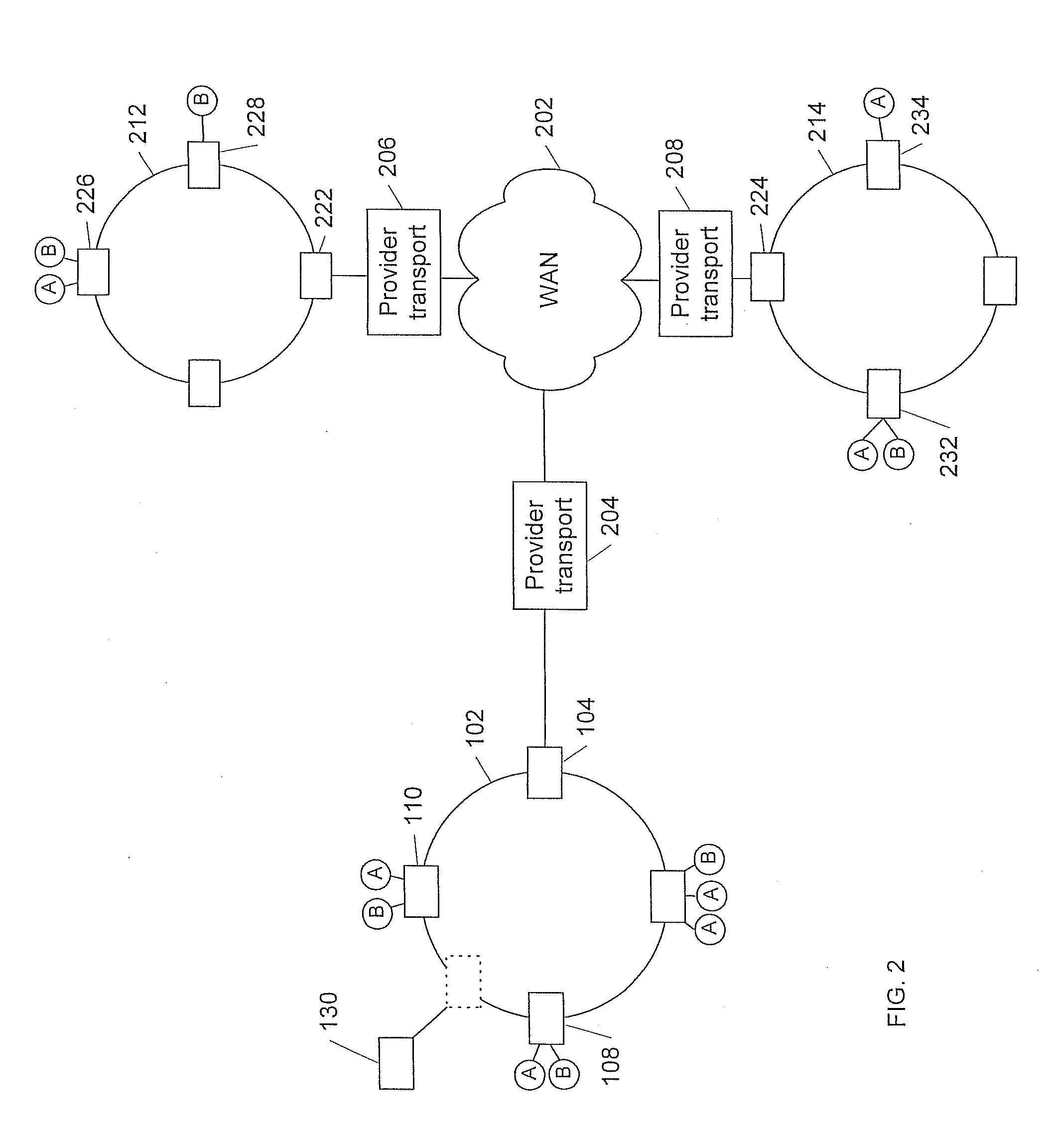
[0026]FIG. 1 illustrates a network 100 in accordance with one embodiment of the present invention. As shown, the network 100 includes a ring 102, which interconnects nodes 104, 106, 108, 110. In one embodiment, the ring 102 may comprise a fiber optic ring having a Resilient Packet Ring (RPR) topology. In some applications, the network 100 may comprise a metro area network (MAN). Each of the nodes 104110 may comprise a high speed routing / multiplexing device. Details of the nodes are described below and in U.S. patent application Ser. No. 09 / 518,956, the disclosure of which is hereby incorporated by reference in its entirety.

[0027]Multiple transparent LAN services (TLS) domains, such as domains A and B may co-exist on the ring 102. A TLS domain may be identified by a port of a slot of a node. As discussed below, each TLS domain has an associated multicast MPLS label; each site within a TLS domain has a unique site ID. Thus, the multicast label may be used to send data to the various p...


PUM


Abstract

A system and method provide transparent LAN services in a metro-WAN environment to extend enterprise LANs over metro and wide area networks. The transparent LAN services generally provide customers with a layer two Ethernet connectivity with MAC learning capabilities.

Description

CROSS-REFERENCE TO RELATED APPLICATION[0001]This patent application claims priority, under 35 U.S.C. 120, as continuation patent application, to commonly assigned U.S. patent application Ser. No. 10 / 140,308, filed on May 6, 2002, entitled “LOGICAL PORT SYSTEM AND METHOD”, which, in turn, is related to U.S. patent application Ser. No. 10 / 140,234, filed on May 6, 2002, entitled “SYSTEM AND METHOD FOR PROVIDING TRANSPARENT LAN SERVICES”, the contents of each being hereby incorporated by reference in their entirety.TECHNICAL FIELD[0002]This invention relates to communication networks, and in particular to a system and method for providing transparent LAN (Local Area Network) services.BACKGROUND OF THE INVENTION[0003]Many network users, such as companies, have multiple sites within a metro area or region and desire to provide “internal” or LAN-like network connectivity between those locations, each of which may comprise an intranet. In addition, some of these network users desire network...

Claims


Application Information

Patent Timeline
IPC IPC(8): H04B10/12H04L12/42H04L12/46H04L12/56
CPCH04L12/42H04L45/50H04L45/308H04L12/4641
Inventor BANNAI, VINAYKARALI, THEODORAJONES, PETER GEOFFREYZOUCHA, JACQUELINE M.SASTRY, ARUN
Owner ADTRAN
Learn More