Cancellation systems for multicarrier transceiver arrays

a transceiver array and multi-carrier technology, applied in the field of cancelation systems for multi-carrier transceiver arrays, can solve the problems of poor cancellation over a broad range of frequency, hoover does not compensate for phase-variation, frequency-dependent amplitude-variation of pick-up responses

Inactive Publication Date: 2006-08-15
S AQUA SEMICONDUCTOR LLC
View PDF4 Cites 28 Cited by
  • Summary
  • Abstract
  • Description
  • Claims
  • Application Information

AI Technical Summary

Benefits of technology

[0022]Embodiments of the invention may optimally combine received frequency components of a single-carrier signal to reconstruct the single-carrier signal.

Problems solved by technology

However, Hoover does not compensate for differences in the pickup coils that cause the amplitude-variation of the pick-up responses to be frequency-dependent.
Thus, Hoover's proposed solution results in poor cancellation over a broad range of frequency.
Furthermore, Hoover does not compensate for phase-variations that occur between different pickup coils.
The resulting cancellation from the unbalancing method is poor.
Hoover does not present an effective method for controlling the phase-response of the system, nor does Hoover present the mathematical relationships between phase and frequency resulting from the driver and pickup coils.
Pospischil does not identify nor compensate for electrical path-length differences (e.g., differences in impedance) that occur between different electromagnetic receivers (pickups).
This technique is not effective for providing a high degree of cancellation because slight differences between the pickups, even pickups that are substantially identical, cause the frequency-dependent amplitude and phase response of the pickups to differ significantly from each other.
However, problems with beam forming include the inability to resolve co-located or closely spaced radio sources unless multipath components of these signals are tracked.
This is a significant problem because each multipath component arriving at the array is a source of interference.
Therefore, a small number of transmitters may provide a large number of interference sources.

Method used


Image

  • Cancellation systems for multicarrier transceiver arrays
  • Cancellation systems for multicarrier transceiver arrays
  • Cancellation systems for multicarrier transceiver arrays

Examples


Embodiment Construction

[0039]In the description of the preferred embodiments, it is assumed that the reader has a familiarity with electromagnetic cancellation, as described in U.S. Pat. Nos. 6,211,671, 6,208,135, and 5,523,526, which are all incorporated by reference.

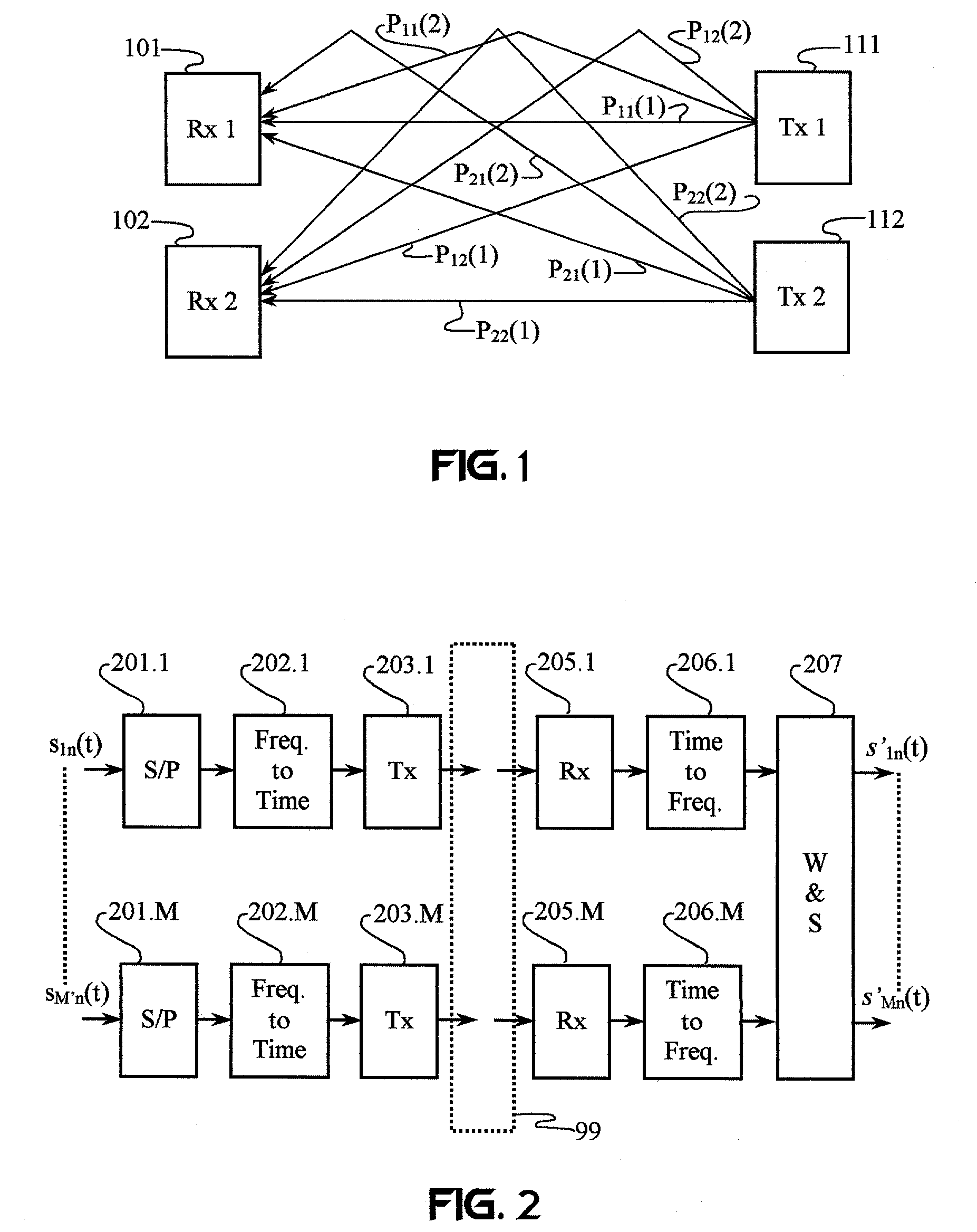
[0040]FIG. 1 illustrates a plurality of spatially separated receivers 101 and 102 adapted to be responsive to electromagnetic signals transmitted by a plurality of spatially separated transmitters 111 and 112. For the purpose of describing the function of a cancellation system, each receiver 101 and 102 is responsive to signals arriving along two transmission paths from the transmitters 111 and 112.

[0041]Transmitter 111 transmits a first signal s1(t) that arrives at receiver 101 from a line-of-sight transmission path P11(1) and a reflected (and thus, delayed) path P11(2). Similarly, transmitter 112 transmits a second signal s2(t) that arrives at receiver 101 from a line-of-sight transmission path P21(1) and a reflected (and thus, delayed) pa...


PUM


Abstract

Frequency-dependent cancellation separates a plurality of interfering signals received by a plurality of receivers. Received wideband single-carrier signals or multicarrier signals are separated into a plurality of narrowband subcarriers. Sub-carrier frequencies and frequency-band characteristics may be selected with respect to channel characteristics (e.g., coherence bandwidth, interference, etc.). A cancellation circuit provides complex weights to the sub-carrier components. Weighted components associated with each sub-carrier frequency are combined to separate a plurality of interfering signals. Optionally, a plurality of the separated subcarriers may be combined to reconstruct at least one transmitted single-carrier signal from a plurality of frequency components. Combining may include decoding, such as to reconstruct a coded sequence of data symbols transmitted via direct-sequence coding, code division multiple access (CDMA), multicarrier CDMA, carrier interferometry (CI), CI coding, or coded orthogonal frequency division multiplexing.

Description

RELATED APPLICATIONS[0001]This application is a continuation-in-part of Ser. No. 09 / 821,547, filed Mar. 29, 2001, now U.S. Pat. No. 6,348,791, which is a division of Ser. No. 09 / 433,196, filed Nov. 3, 1999, now U.S. Pat. No. 6,211,671, which is a division of Ser. No. 08 / 279,050, filed Jul. 22, 1994, now U.S. Pat. No. 6,208,135, which is a continuation-in-part of application Ser. No. 08 / 097,272, filed Jul. 23, 1993, now U.S. Pat. No. 5,523,526.BACKGROUND OF THE INVENTION[0002]I. Field of the Invention[0003]The present invention relates to applications of active electromagnetic shielding to electromagnetic receivers for canceling undesired, interfering signals.[0004]II. Description of the Related Art[0005]It has long been known that voltages are induced in all conductors exposed to changing magnetic fields regardless of the configuration of such conductors. Electromagnetic radiation will induce electrical signals in electronic devices according to the laws of magnetic induction. Thus,...

Claims


Application Information

Patent Timeline
Patent Type & Authority Patents(United States)
IPC IPC(8): H04J11/00H05K9/00
CPCH04B7/0857H05K9/00H04L2025/03426H04L2025/03414
Inventor SHATTIL, STEVE J.
Owner S AQUA SEMICONDUCTOR LLC
Why Eureka
Try Eureka