Method and apparatus of automatic scanning probe imaging

a scanning probe and automatic technology, applied in the direction of instruments, surface/boundary effects, measurement devices, etc., can solve the problems of inability of experienced afm inability to establish correlation during real time imaging, and inability of operators to make real time decisions about zooming in the area. achieve the effect of automatic identification, positive identification of features, and greater resolution

Active Publication Date: 2009-03-19
BRUKER NANO INC
View PDF11 Cites 25 Cited by
  • Summary
  • Abstract
  • Description
  • Claims
  • Application Information

AI Technical Summary

Benefits of technology

[0024]One key advantage of the invention is automatically identifying the desired feature during large area survey scans. Feature detection uses multi-dimensional data, including the feedback response in trace / re-trace scanning, as well as phase and amplitude data. The real time analysis of the multi-dimensional data results in positive identification of the feature. The coordinates and the properties of the feature are then used to perform a high resolution measurement of the feature at an appropriate zoom-in scan size and speed, automatically. Feature detection occurs over an area achievable by a piezo scanner and through an offset of a motorized stage. The automation process also includes setting scanner control through use of an inversion-based iterative feed forward algorithm, as well as setting imaging parameters for the cantilever feedback control and automatically engaging and disengaging the AFM tip.
[0025]According to an aspect of the preferred embodiment, a probe-based instrument for identifying and providing greater resolution for one or more sample features is described. The instrument includes a scanning probe microscope (SPM), the SPM including a probe having a cantilever bearing a tip, a feature identification engine configured to identify a sub-section of the sample, the sub-section including a feature detected based on the sample surface data using at least two identification parameters, and a feature scanning controller, the feature scanning controller configured to provide control signals to the SPM to scan the sub-section of the sample at a second resolution as a probe of the SPM interacts with the sub-section of the sample, the second resolution being greater than the first resolution.
[0026]According to another aspect of the preferred embodiments, a method of operating a scanning probe microscope (SPM) including scanning a sample at a first resolution as a probe of the SPM interacts with a sample and collecting sample surface data in response to the scanning step. The method then, during collection of the sample surface data, identifies a feature of the sample from the sample surface data using at least two identification parameters and automatically performs a zoom-in scan of the feature at a second resolution based on the identifying step, the second resolution being greater than the first resolution.
[0027]In another aspect of the preferred embodiments, the identifying step includes confirming the authenticity of the feature, and the confirming step includes analyzing trace and re-trace data sets of the sample surface data using one or more verification tests.
[0028]According to a further aspect of the preferred embodiments, the confirming step includes at least one of analyzing trace and re-trace data sets of the sample surface data, confirming authenticity based on a principle component analysis of a neural network, and comparing a known pattern with the feature by pattern recognition analysis.
[0029]According to another exemplary embodiment of the preferred embodiments, a method of operating a scanning probe microscope (SPM) to identify and provide greater resolution for one or more sample features is described. The method includes performing a survey scan of a sample at a frequency of at least 5 Hz to generate sample surface data at a first resolution based on interaction between a probe of the SPM and the sample, identifying a sub-section of the sample including a feature having a height greater than about 1 nanometer, verifying the sub-section to identify the feature from noise using at least two verification tests including at least one of feedback inverse correlation testing, pattern match testing, and reverse symmetry testing, and performing a data scan of the verified sub-section of the sample at a second resolution as a probe of the SPM interacts with the sub-section of the sample, the second resolution being greater than the first resolution.

Problems solved by technology

Though an experienced operator can usually determine a zoom-in location, due to the noise and occasional instability of the feedback loop, even an experience operator can misjudge the asperity event when analyzing data corresponding to a few pixels.
In the end, even experienced AFM operators are not suitably effective to make a real time decision of the zoom in the area when attempting to identify small-scale features such as nano-asperities.
Such correlation is impossible for the operator to establish during real time imaging, and unfortunately is effectively useless if performed offline since the tip may not be able to be reliably positioned at location because of drifting and hysteresis effects.

Method used


Image

  • Method and apparatus of automatic scanning probe imaging
  • Method and apparatus of automatic scanning probe imaging
  • Method and apparatus of automatic scanning probe imaging

Examples


Embodiment Construction

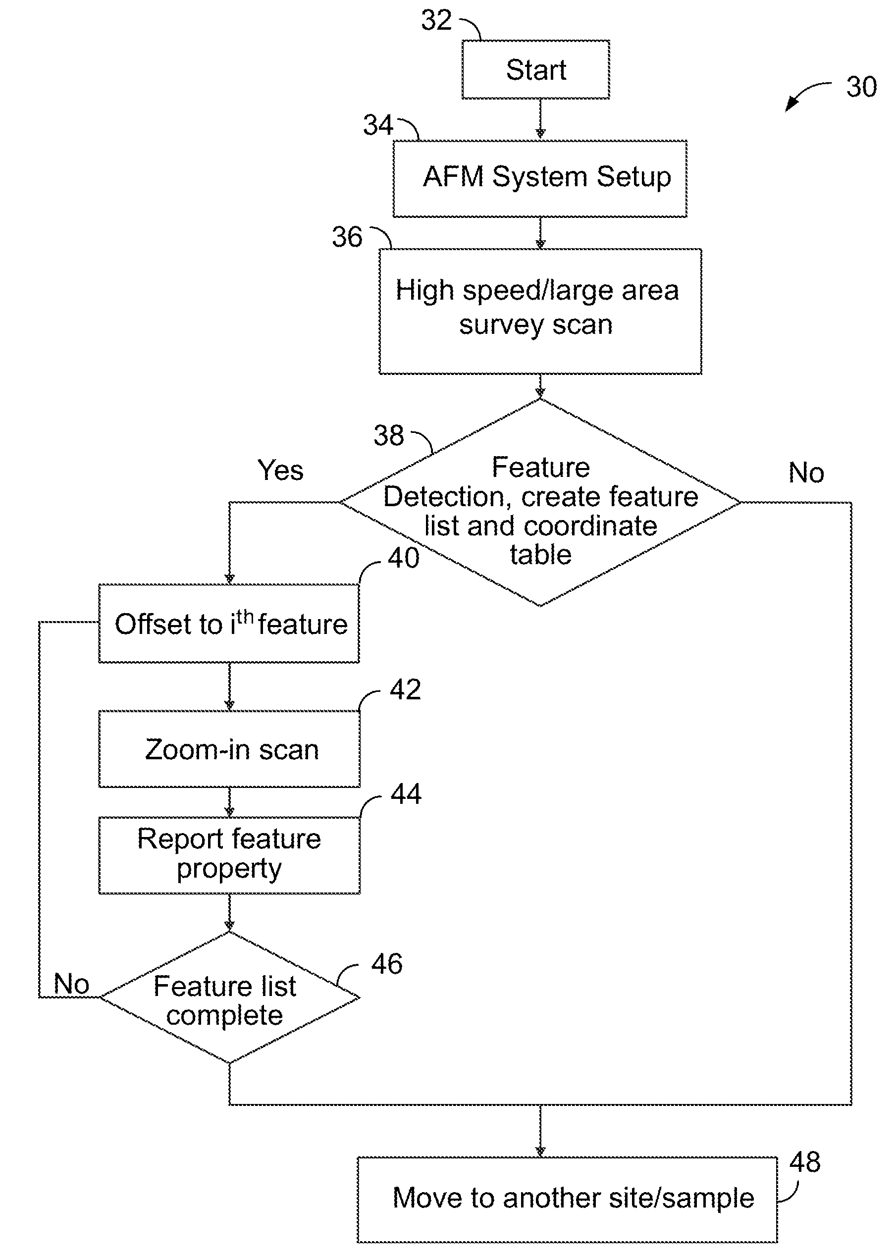
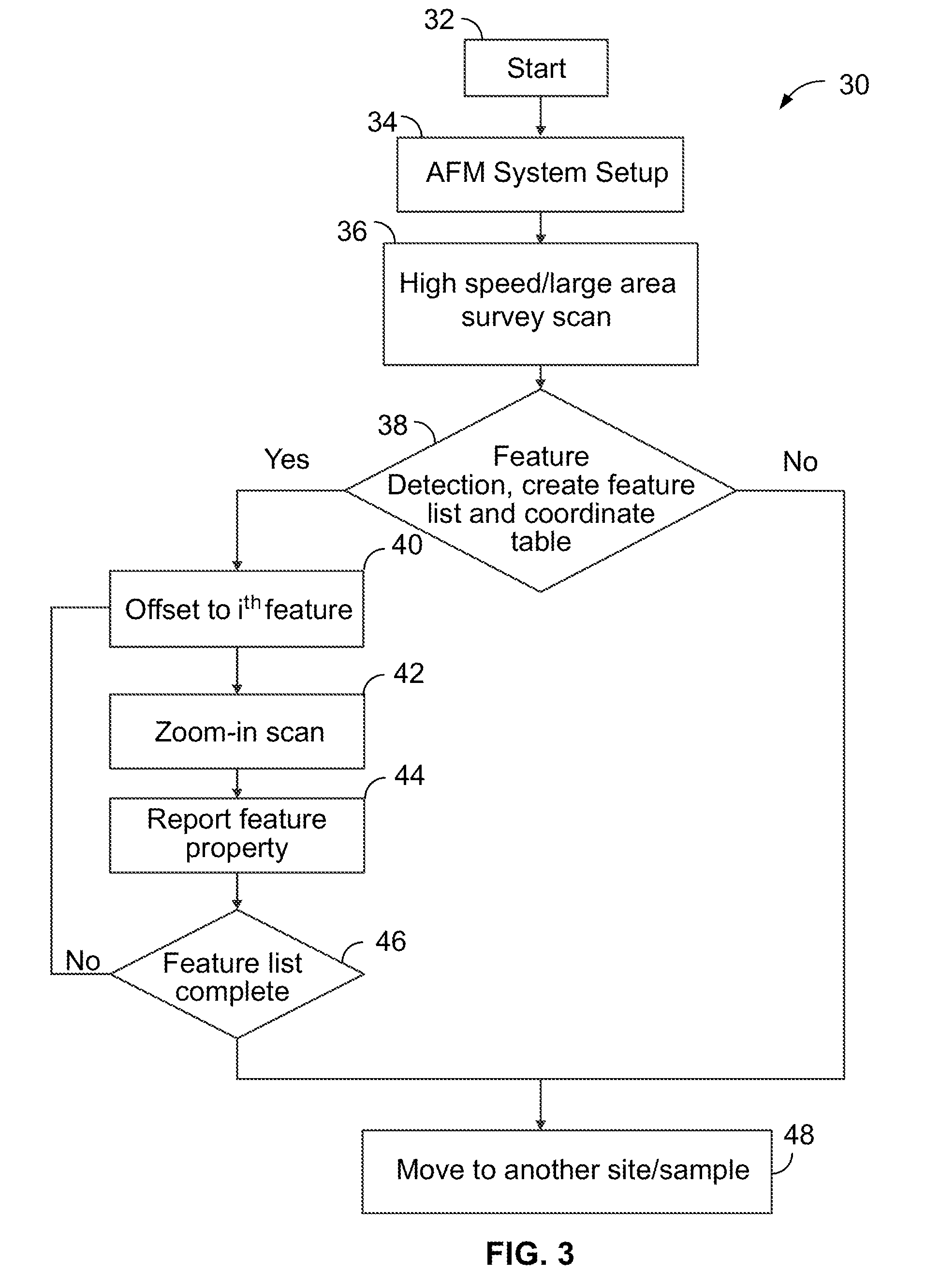
[0045]Referring initially to FIG. 3, the automatic imaging process 30 of the preferred embodiments contains the following steps. According to an exemplary embodiment, process 30 may be implemented using a feature identification engine implemented in software, hardware or firmware and configured to implement the methods described herein. According to the exemplary embodiment, the feature identification engine may be implemented as a software process within AFM Control / Computer 20, and will use multi-dimensional data including, for example, amplitude, phase, deflection, trace and retrace data, etc. during realtime imaging to identify the feature of interest and distinguish the identified feature of interest from other data such as noise. After a start-up and initialization step in Block 32, the state of an imaging operation includes having the system automatically set cantilever probe operating parameters in Block 34. AFM system set-up includes engaging probe with the sample so as to ...


PUM

PropertyMeasurementUnit
frequencyaaaaaaaaaa
heightaaaaaaaaaa
scan sizeaaaaaaaaaa

Abstract

A method of operating a scanning probe microscope (SPM) includes scanning a sample as a probe of the SPM interacts with a sample, and collecting sample surface data in response to the scanning step. The method identifies a feature of the sample from the sample surface data and automatically performs a zoom-in scan of the feature based on the identifying step. The method operates to quickly identify and confirm the location of features of interest, such as nano-asperities, so as to facilitate performing a directed high resolution image of the feature.

Description

CROSS-REFERENCE TO RELATED APPLICATION[0001]This application claims the benefit of U.S. Provisional Application No. 60 / 971,828, filed Sep. 12, 2007, incorporated herein by reference in its entirety.BACKGROUND OF THE INVENTION[0002]1. Field of the Invention[0003]The preferred embodiments are directed to a method of imaging a sample using a scanning probe microscope (SPM), and more particularly, a method for automatically recognizing and verifying small-scale sample features, such as nano-asperities, with the SPM at high image resolution and scan rates.[0004]2. Discussion of the Prior Art[0005]A scanning probe microscope, such as an atomic force microscope (AFM) operates by providing relative scanning movement between a measuring probe and a sample while measuring one or more properties of the sample. A typical AFM system is shown schematically in FIG. 1. An AFM 10 employing a probe device 12 including a probe 14 having a cantilever 15 is shown. A scanner 24 generates relative motion ...

Claims


Application Information

Patent Timeline
Patent Type & Authority Applications(United States)
IPC IPC(8): G12B21/02G01N13/10G01Q30/04G01Q60/00G01Q60/24G01Q70/00
CPCB82Y35/00Y10S977/85G01Q30/04G01Q10/06G01B21/30G01Q10/04G01Q20/02
Inventor SU, CHANMINBELIKOV, SERGEY
Owner BRUKER NANO INC
Why Eureka
Try Eureka