Automated cascade impactor

a cascade impactor and automatic technology, applied in the field of fluid measurement of particle size, can solve the problems of manual process, high operator-induced variability in the data produced, and low throughput of obtaining particle size distribution data using conventional cascade impactors, so as to achieve accurate measurement, easy and economical manufacturing, and operation

Active Publication Date: 2009-03-26
LAB AUTOMATE TECH
View PDF5 Cites 9 Cited by
  • Summary
  • Abstract
  • Description
  • Claims
  • Application Information

AI Technical Summary

Benefits of technology

[0015]Embodiments disclosed herein significantly overcome such deficiencies and provide an Automated Cascade Impactor that allows multiple Dose Determinations per day, and substantially eliminates the operator induced variability associated with subsequent Dose Determinations. In particular, the methods and apparatus describe herein provide a robotic automated cascade impactor that provides automation of the process of coupling the impactor stages together during delivery of a sample dose, as well as automation of collection of the drug sample from each impactor stage and cleaning each impactor stage.
[0025]In an example embodiment disclosed herein, the Automated Cascade Impactor provides a mechanism that is easy and economical to manufacture, and operate.
[0026]In an example embodiment disclosed herein, the Automated Cascade Impactor sandwiches, between Impactor Stages, an imaging system that takes images of the orifices, so that the diameters of the orifices may be accurately measured.
[0027]In example embodiment disclosed herein, the Automated Andersen Impactor automates the determination of particle size distribution, using the Automated Cascade Impactor into which samples are injected. In one configuration, the impactor stages mounted within the impactor mounts are those of a conventional Andersen Cascade Impactor, thus producing an Automated Andersen Cascade Impactor. In the Automated Andersen Cascade Impactor, the length of the Automated Cascade Impactor column (when the extension mechanism compresses only the impactor stages) remains unaltered (as compared to a manual conventional impactor, such as an Andersen Cascade Impactor) for delivery of the sample into the Automated Andersen Cascade Impactor using an aerosolized inhalation device, or any other device for that matter. Thus, the flight time and the path of the particles inside the Automated Andersen Cascade Impactor remain unaltered. This negates the need to perform bridging studies (had the Andersen Column been altered) with respect to current data. For the same reason, comparison of particle size distribution with data associated with other studies remains the same (i.e., bridging studies are not required).

Problems solved by technology

Conventional technologies for obtaining particle size distribution data using conventional cascade impactors suffer from a variety of deficiencies.
In particular, obtaining particle size distribution using conventional impactors provides very low throughput since conventional impactors rely on completely manual setup, operation, testing and dose determination.
Additionally, the manual process is very prone to a great degree of operator induced variability in the data produced.
Each operator (e.g. lab technician or analyst) washes the many components of the Andersen Cascade Impactor a little differently, thus causing inconsistency in the amount of drug collected from each stage and each Impaction plate.
This inconsistent human washing of the plurality of impactor surfaces further affects the recovery of a drug from the same apparatus for subsequent Dose Determinations.
This operator induced variability precipitates the need for additional Dose Determinations that cause delay in submission of data by the drug companies to the FDA, and thus also delay the approval of drugs by the FDA.
Delays due to operator induced variability, and low throughput due to manual operations of the ACI can cause the loss of hundreds of millions of dollars in lost revenue.

Method used


Image

  • Automated cascade impactor
  • Automated cascade impactor
  • Automated cascade impactor

Examples


Embodiment Construction

[0044]Embodiments disclosed herein provide an Automated Cascade Impactor that allows multiple Dose Determinations per day in a manner that is much faster than manual operation of a conventional cascade impactor, and substantially eliminates the operator induced variability associated with the current and subsequent Dose Determinations.

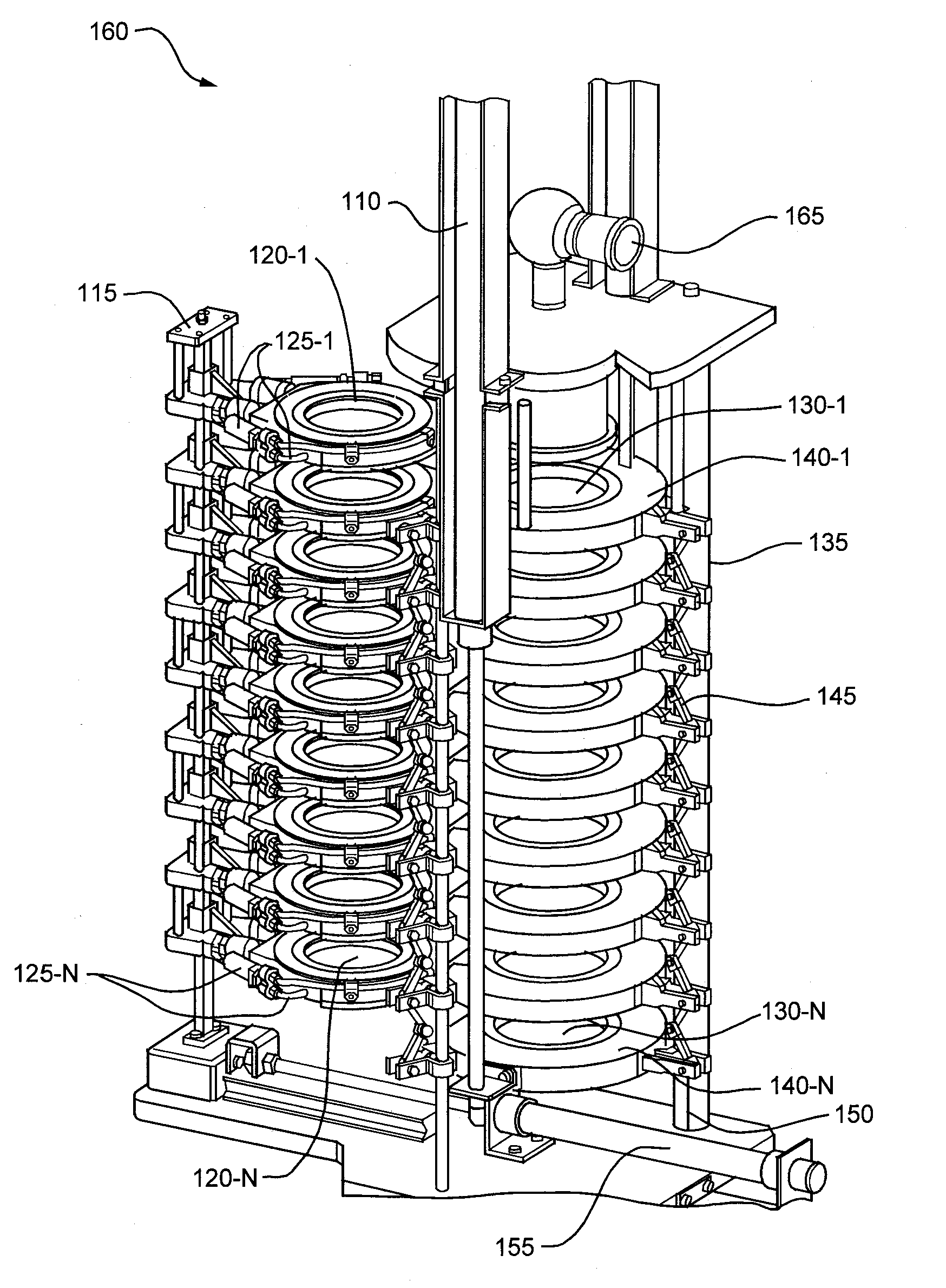
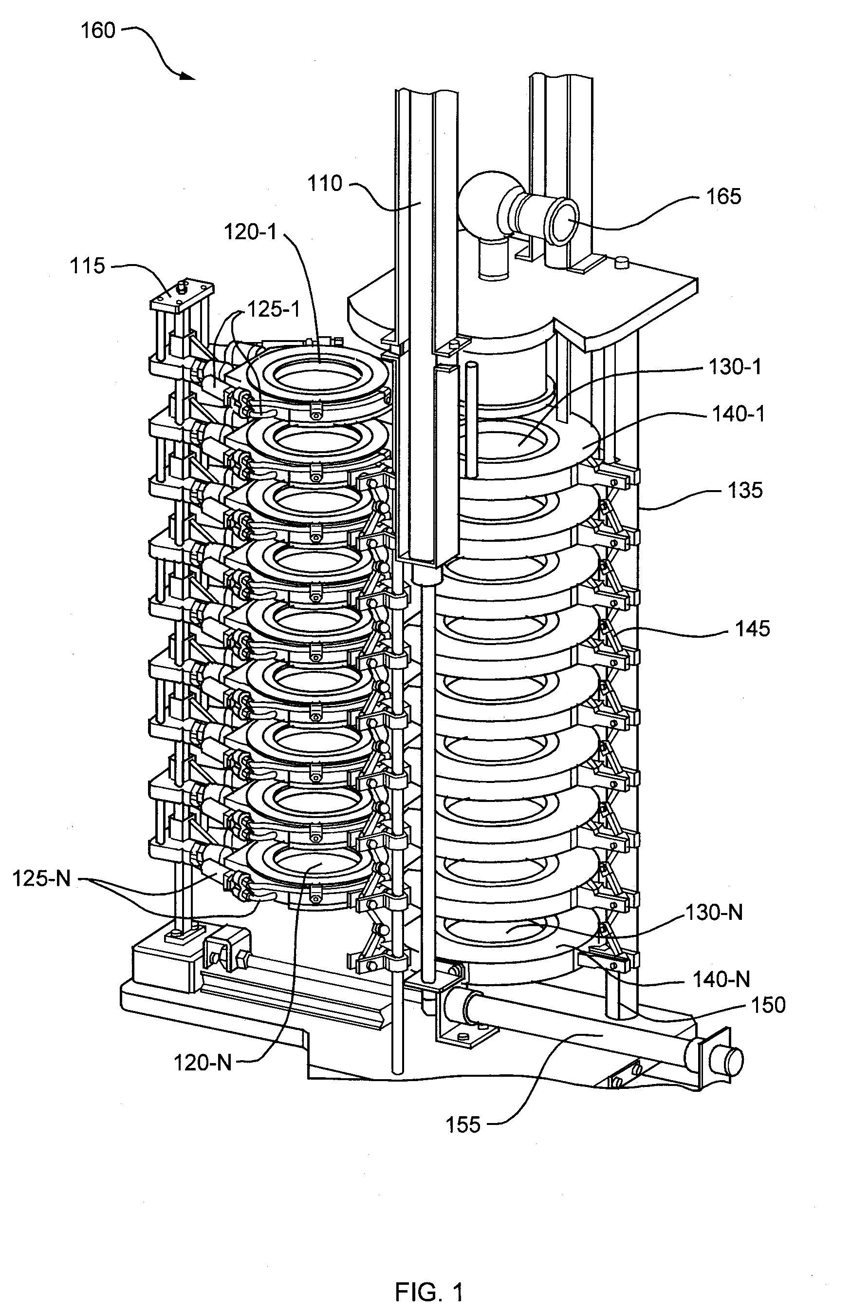
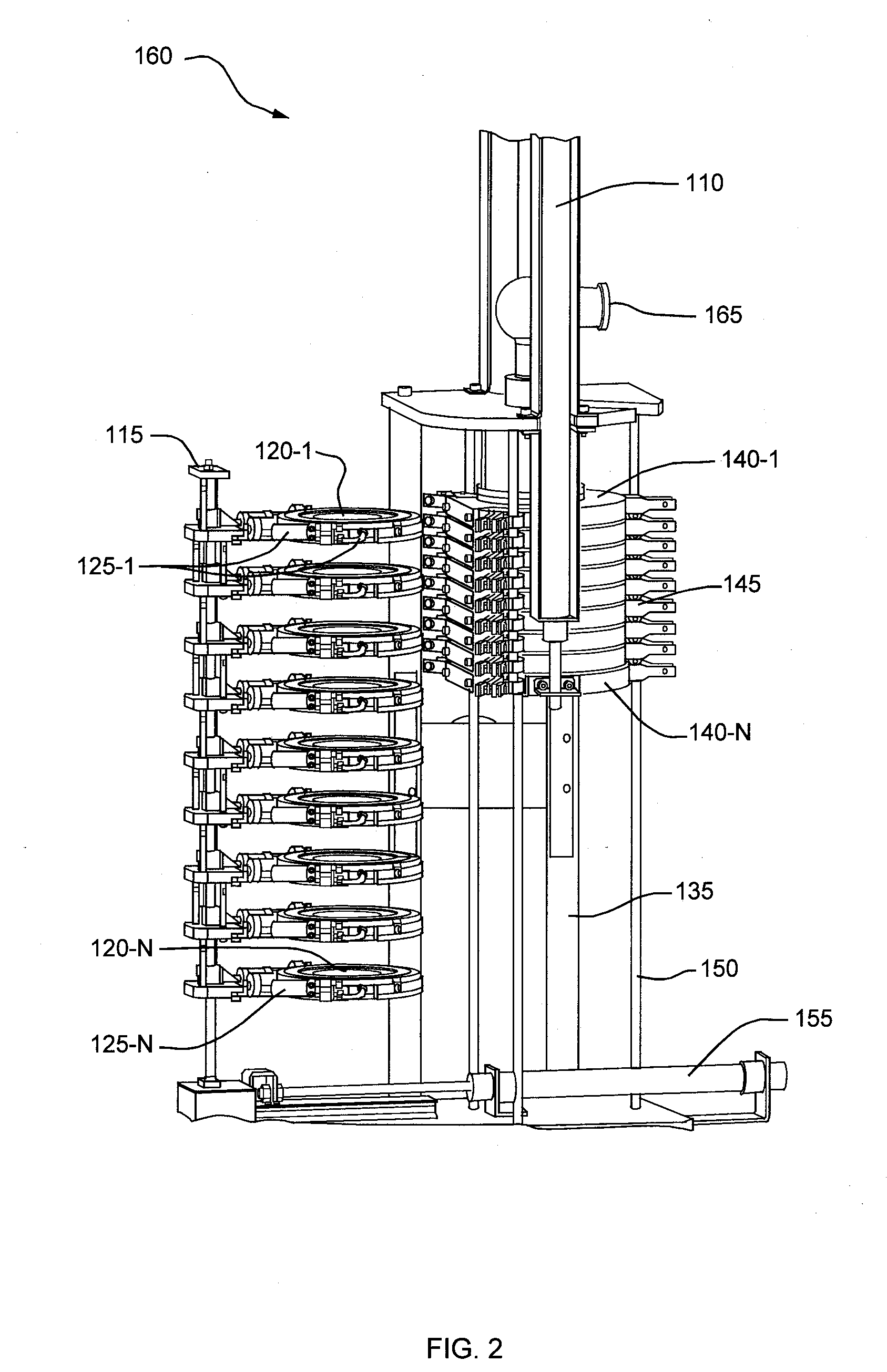
[0045]FIG. 1 illustrates an example embodiment of the Automated Cascade Impactor 160 used to test Dose Determination via an entry throat 165 that is coupled (as will be shown in successive figures) to an uppermost impactor stage 130-1 during compression of the plurality of impactor stages 130-N. The entry throat 165 allows coupling of a delivery device, such as an inhaler (not shown), for dispensing of particulate matter such a drug particulates in an aerosol spray (through the entry throat 165 into the plurality of compressed impactor stages 130-N). In one example embodiment, the entry throat 165 is exchangeable. The Automated Cascade Impactor 160 fur...


PUM

PropertyMeasurementUnit
diameteraaaaaaaaaa
Particle sizesaaaaaaaaaa
timeaaaaaaaaaa

Abstract

An automated cascade impactor comprises an extension mechanism operable to couple to a plurality of impactor stages. The extension mechanism is operable to compress and separate impactor stages of the plurality of impactor stages via automation. The system provides a plurality of isolation stages operable to be automatically inserted between respective impactor stages when the impactor stages are separated by the extension mechanism. The system provides the plurality of isolation stages to be automatically compressed between impactor stages to isolate each impactor stage from at least one adjacent impactor stage. The plurality of isolation stages is operable to be automatically uncompressed and removed from between the impactor stages. The isolation stages allow automated extraction of particulate matter, cleaning and drying of interior surfaces of each impactor stage.

Description

CROSS REFERENCE TO RELATED APPLICATIONS[0001]This patent application claims priority to International Application PCT / US2007 / 08924 filed on Apr. 10, 2007 which claims priority to Provisional Application 60 / 744,663 filed on Apr. 11, 2006, entitled, “AUTOMATED CASCADE IMPACTOR”, the contents and teachings of which are hereby incorporated by reference in their entirety.FIELD OF INVENTION[0002]Embodiments disclosed herein relate to the field of measurement of particle sizes in fluids. Example embodiments include devices and methods for measurement of particle sizes in an air sample, wherever the sample is derived. More specifically embodiments disclosed herein are related to measurement of particle sizes from dose samples of inhalation devices.BACKGROUND OF THE INVENTION[0003]A conventional Cascade Impactor is a device used to determine the aerodynamic particle size distribution and mass concentration levels of solid particulates and liquid aerosols, from aerosolized dry powder and aero...

Claims


Application Information

Patent Timeline
Patent Type & Authority Applications(United States)
IPC IPC(8): G01N1/10
CPCG01N1/2208G01N2015/0261G01N15/0255
Inventor MAHESHWARI, KRISHNA
Owner LAB AUTOMATE TECH
Why Eureka
Try Eureka