
Method of initiating external explosive charges and explosive-charged action elements for these.

a technology of action elements and explosive charges, which is applied in the direction of weapons, ammunition projectiles, projectiles, etc., can solve the problems of large splinters, large cost of weapon systems as a whole reduce the size of the action element, and achieve high initial speed

Inactive Publication Date: 2009-03-26
BAE SYST BOFORS
View PDF10 Cites 7 Cited by
  • Summary
  • Abstract
  • Description
  • Claims
  • Application Information

AI Technical Summary

Benefits of technology

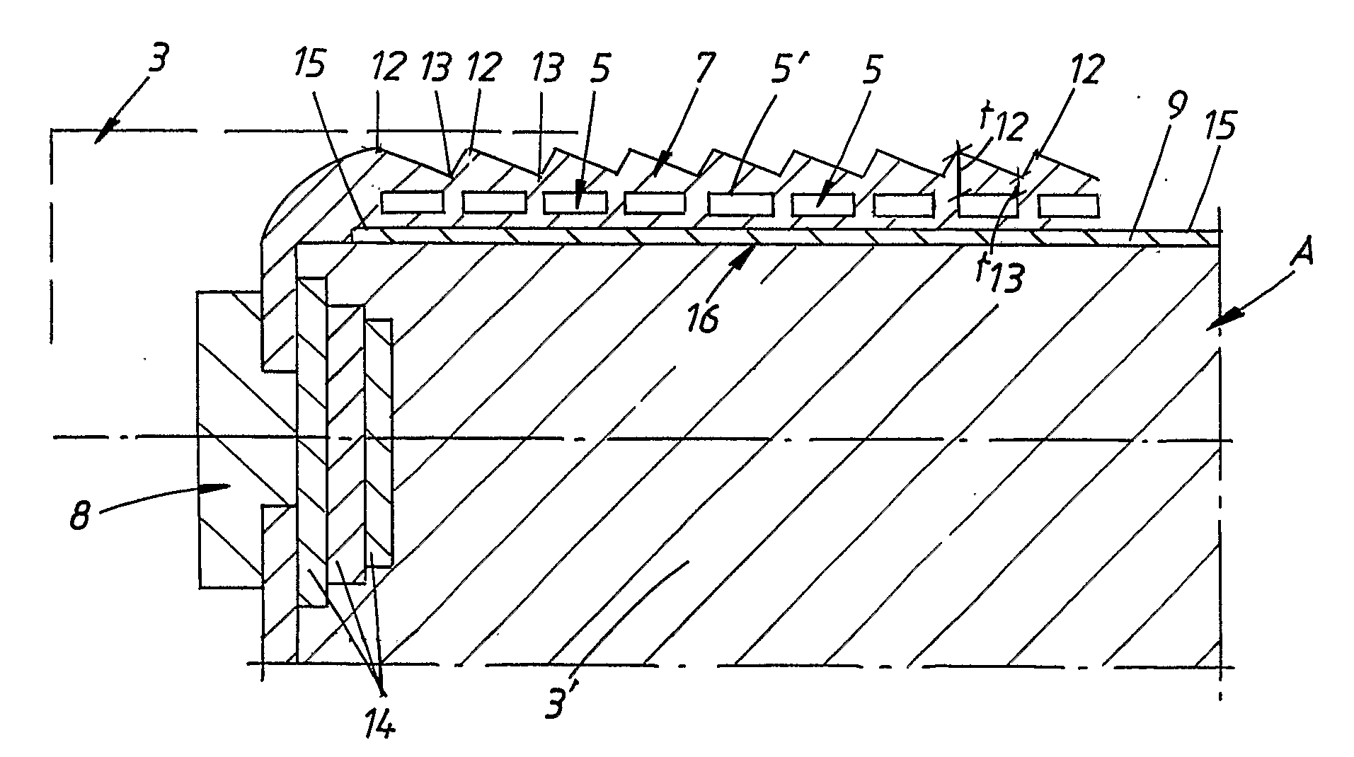
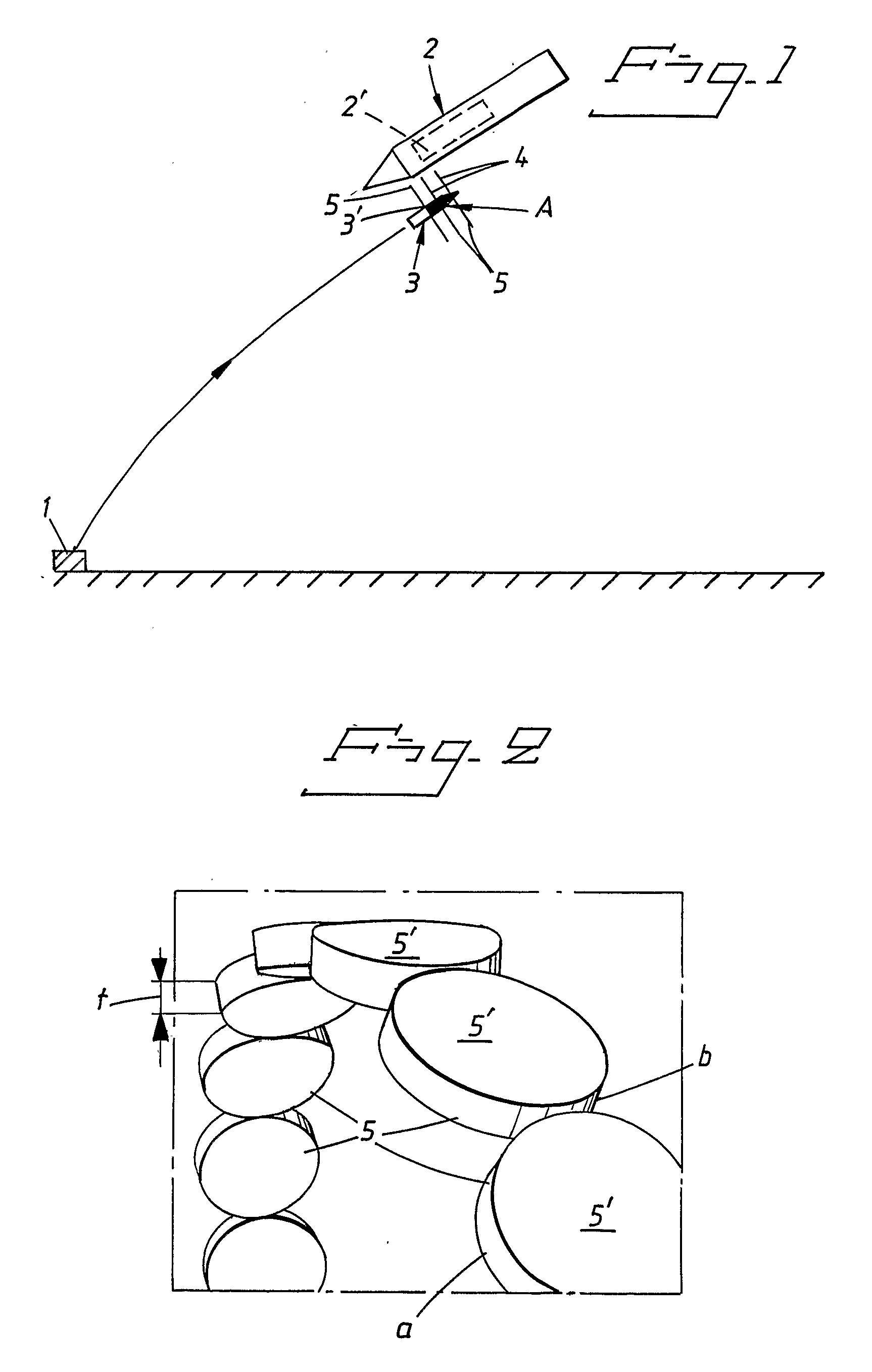
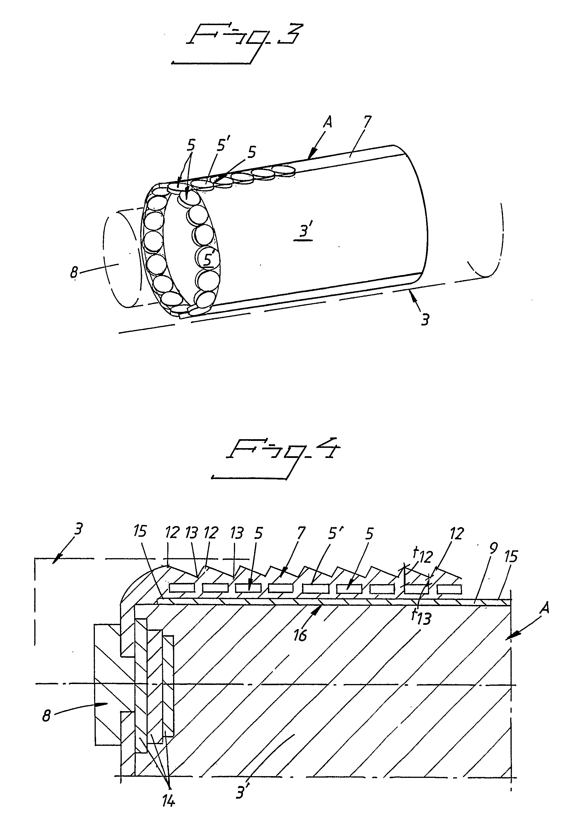
[0029]The basic concept behind the present invention is thus to configure the components forming part of the own action element so that the splinter bodies shaped by the splinter shell of the own action element acquires, compared with their own mass, a large surface facing in the direction of an incoming enemy missile, shell, bomb, craft, etc. and a correspondingly small thickness in the same direction, which means that that side of the splinter bodies, hereinafter referred to as the broadside, which is directed towards and hits the incoming enemy missile, etc., comprising the above and below named first external explosive charge, shall have the shape of laminae, plates, discs, ellipsoids or equivalent. The invention further includes an assurance that these splinters of laminar, plate-like, ellipsoid or other equivalent configuration shall hit the intended target at a sufficiently high speed with their own broadside first and, in so doing, transfer a sufficient kinetic impulse to the explosive charge of the first incoming enemy missile over a sufficient area to initiate the explosive to detonation. This specific configuration of the splinter bodies thus offers a possibility of hitting the target with splinter bodies which, in the event of a hit, provided that they have thus initially been given a sufficiently high speed and despite their limited own mass, transfer a sufficient quantity of kinetic impulse over a sufficient area of explosive to ensure an initiation of the explosive charge forming part of the combated missile. By impulse is here meant, in somewhat simplified terms, a change in the momentum, i.e. the product of mass times speed in a certain direction, of an object.
[0030]Since the above-indicated shape of the splinter bodies configured according to the invention has been able to be given a large surface compared with their own mass, the splinter-forming shell of the action element has been able to be made thinner and hence lighter, whilst, at the same time, a correspondingly lesser amount of detonating charge of explosive inside the splinter-forming shell will be needed to give the splinter bodies released therefrom upon detonation of the explosive charge a sufficiently high initial speed in the direction of the target, i.e. of the foreign missile. This general basic notion thus offers the prospect of markedly reducing the size of the action element which is necessary to combat foreign incoming explosive-charged missiles, and hence the size of the entire weapon system in question and the costs of the same.
[0031]In order for the laminar, plate-shaped or ellipsoidal, etc. splinters to produce the effect outlined above, it is required, however, that, firstly, they maintain their original shape until hitting the target and, secondly, they actually hit the target with their broadside first.
[0032]The first of the above-specified conditions means that the splinter shell from which the splinters are released, upon detonation of the explosive charge disposed inside the splinter shell, is fragmented only at precisely those points and along those parting lines which were originally presumed, and this can be ensured by means of weaker sections, for example in the form of material thinnings, at the said points and along the desired parting lines, built from the outset into the splinter shell. A better solution to the same problem is, however, to produce the splinter shell by powder metallurgy methods, pre-produced splinter bodies being inserted into a matrix, produced by powder-metallurgy methods, which separates the splinter bodies one from another and from the explosive charge and which, by virtue of the fact that the matrix, upon detonation of the explosive, surrounds the splinter bodies, gives these a gentle acceleration, which prevents the splinter bodies from fragmenting and ensures that these are accelerated in the desired direction, namely in the direction of the incoming enemy missile, etc. This process for the production of the splinter shells therefore has the advantage that, by producing the splinter bodies separately, it is possible to give them the most favourable configuration for each individual case and, moreover, to give them a substantially higher strength than the matrix material which initially holds the splinter shell together. Consequently, it is thus possible effectively to prevent an undesirable fragmentation of the splinter bodies and to ensure that these, when they are released from the splinter shell and begin their flight towards the target, acquire precisely that configuration which is designed for the purpose.
[0033]The division of the splinter shell into splinter bodies of a desired shape, irrespective of whether the splinter shell is produced by powder-metallurgical methods or not, might also be to some extent ensured by specific counterstaying elements disposed on the outside of the splinter shell along desired rupture lines between the desired splinter bodies.
[0034]In order to reinforce and further ensure the division of the splinter shell into splinter bodies of desired size and shape along predetermined rupture lines or along the space between prefabricated splinter bodies baked into a powder-metallurgical matrix, and in order, at the same time, to prevent an undesirable further fragmentation of the splinter bodies, the inner side of the splinter shell can be provided with shock wave traps in the form of one or more layers of linings of material which exhibits strongly different acoustic properties from the rest of the splinter shell. As examples of materials which can be used as such shock wave traps, plastics of different hardness and density can be cited.

Problems solved by technology

The drawback with this approach has previously been that large splinters which hit the explosive charge of the incoming missile at high speed have been needed to ensure that this would be initiated to detonation.
This gave rise to the need to provide the own anti-missile second missile with a large action element comprising a thick splinter-forming outer shell and a powerful explosive charge fragmenting the splinter shell, which automatically meant that the weapon system as a whole became large and expensive.

Method used


Image

  • Method of initiating external explosive charges and explosive-charged action elements for these.
  • Method of initiating external explosive charges and explosive-charged action elements for these.
  • Method of initiating external explosive charges and explosive-charged action elements for these.

Examples


Embodiment Construction

[0049]FIG. 1 shows diagrammatically and specifically an explosive-charged enemy missile 2 incoming towards a target 1, hereinafter referred to as the first missile 2. For combating of this first missile 2, an own missile 3 equipped according to the present invention, hereinafter referred to as the second missile 3, has been launched, or alternatively fired, from another carrier such as an aeroplane, which second missile comprises an action element A, see FIG. 3. This second missile 3 does not need to hit the first missile 2 in order wholly to be able to eliminate this. In the nearest position of the second missile 3 relative to the first missile 2, a charge with explosive 3′, which charge forms part of the second missile 3, is instead initiated, splinters 4 configured according to the invention being dispatched in a swarm towards the first missile 2. In the event of a hit upon the explosive charge 2′ of the first missile 2, this external explosive charge 2′ is initiated by the said ...


PUM


Abstract

The present invention relates to a method of initiating explosive charges by means of splinter bodies (5) directed towards these at high speed by an external explosion. According to the invention, these splinter bodies (5) are given large surfaces or broadsides compared with their own mass and are forced to hit the explosive charge with their broadsides (5′) first in order thereby to transfer sufficient kinetic impulse energy to initiate the explosive charge. The invention also comprises splinter bodies (5) specially configured for the implementation of the said method of initiating explosive-filled bodies (2) and explosive charges (3′), intended for the implementation of the said method and provided with a splinter shell (7) comprising the type of splinter bodies (5) characteristic of the invention.

Description

TECHNICAL FIELD[0001]The present invention relates to a method of initiating at least one first external explosive charge by means of a kinetic impulse which is transferred to the said first external explosive charge by splinter bodies, directed towards this first external explosive charge and flying freely at high speed, which have separated from a second explosive-filled action element A, initiated on own initiative and provided with an outer shell which surrounds the explosive and, upon detonation thereof, forms splinters.[0002]The invention also relates to an explosive-charged action element A, provided with a splinter-forming outer shell, intended to release, upon detonation of its own explosive charge, splinter bodies flying freely at high speed and intended to be used, according to the method according to the invention, to initiate at least one external explosive charge by transferring a sufficient quantity of kinetic impulse to the said external explosive charge to initiate ...

Claims


Application Information

Patent Timeline
Patent Type & Authority Applications(United States)
IPC IPC(8): F42B12/22
CPCF41H11/02F42B12/60F42B12/32F42B12/02F42B12/56
Inventor RONN, TORSTEN
Owner BAE SYST BOFORS
Learn More