
Vibration damping device

a damping device and vibration technology, applied in the direction of shock absorbers, springs/dampers, vibration suppression adjustments, etc., can solve the problems of inability to meet the requirements of many applications, devices are too heavy, and are not always acceptable in many applications. , to achieve the effect of high efficiency, low weight and high efficiency

Inactive Publication Date: 2009-03-26
UNIV DEGLI STUDI DI ROMA LA SAPIENZA
View PDF12 Cites 19 Cited by
  • Summary
  • Abstract
  • Description
  • Claims
  • Application Information

AI Technical Summary

Benefits of technology

[0006]It is therefore an objective of the invention to provide a vibration damping device which overcomes the drawbacks set forth and achieves a very high efficiency in a manner that it brings the magnitude of the vibration displacement of the body below the desired level in a very short time after the application of the impulse, such that it can be considered as nearly immediate from a practical point of view. Another objective of the invention is to provide a damping device which has a high efficiency, while maintaining a very low weight.
[0008]The vibration device according to the invention is very simple and versatile since its application can be applied to different fields of engineering with a very high damping efficiency, regardless of the size of the vibrating structures to which it is applied.
[0010]This has the advantage of reducing the global structure weight of main structure and vibration damper, with the advantage that the damping device of the invention can be used in particularly demanding applications like on flying or spatial vehicles.
[0011]Moreover, the damping device is able to produce the desired damping effect, even in the absence of any source of energy dissipation by means of a viscous effect. The energy is permanently transferred from the vibrating master structure to the damping device because of its special design.
[0012]Thus, a damping device using this principle can be used to effectively damp the motion, either vibration or oscillation, of a large structure, conferring characteristics of lightness of the device itself, that cannot be achieved with traditional damping means.
[0020]7) a system for damping the motion of a floating vessel moved by waves and the simultaneous energy recovering from waves.

Problems solved by technology

The results achieved by means of this damping device are not satisfactory.
However, in order to achieve a rapid damping effect such devices are too heavy, which is not always acceptable in many application, e.g. on spatial or flying vehicles.

Method used


Image

  • Vibration damping device
  • Vibration damping device
  • Vibration damping device

Examples


Embodiment Construction

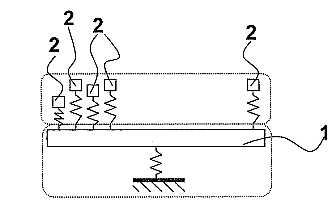
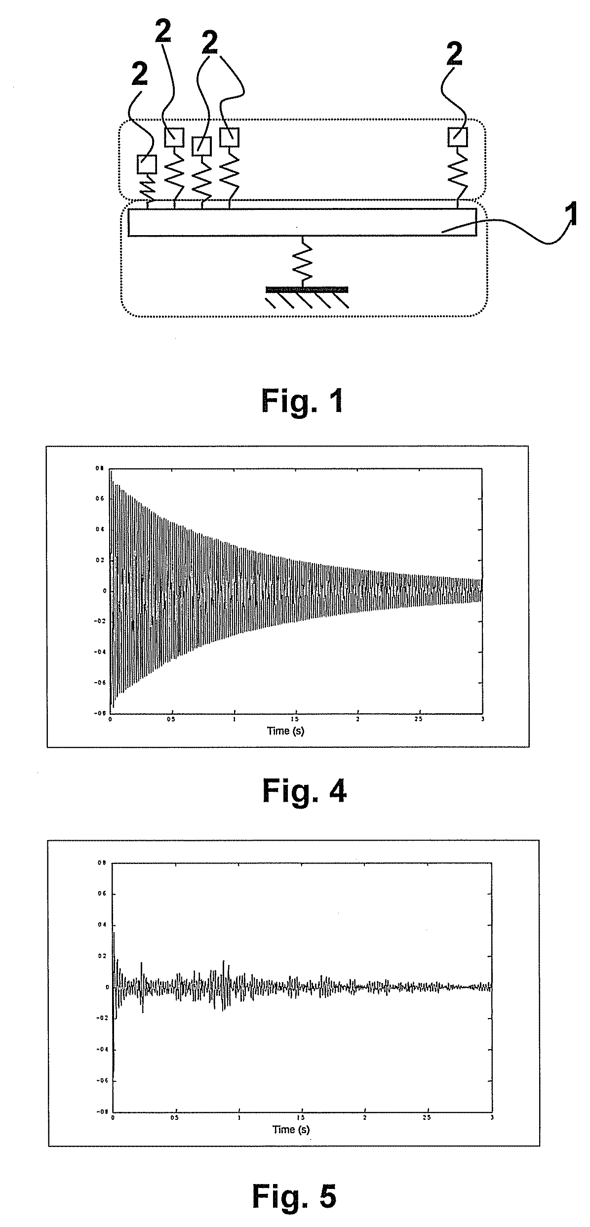
[0049]The FIG. 1 shows, for purpose of illustration, the basic scheme of the damping device according to the invention. A plurality of resonators 2, having a predefined frequency distribution, are connected in parallel to a common principal or “master” structure 1. An impulse applied to the master structure 1, here represented for the sake of simplicity by a single-degree-of-freedom system, starts the motion of the master structure 1, but its energy is progressively released to the set of resonators 2 that begin to vibrate.

[0050]The observation of the motion of the master structure 1, shows that it appears damped due to its transfer of energy to the set of resonators 2.

[0051]The motion of the resonators is initially phase-coherent causing an energy transfer from the master structure 1 to the set or cluster of resonators 2; subsequently, the motion of the resonators 2 becomes phase-incoherent so that the net force from the cluster to the master becomes almost zero preventing in this ...


PUM


Abstract

The damping device comprises a cluster of resonators with a predetermined frequency distribution, that, when attached to a main or “master” structure, is capable of absorbing irreversibly its vibrational or / and acoustic energy produced by a vi 5 brating body. the density of natural frequencies of the plurality of resonators is comprised within a curve that lies below the envelope curve determined by the formula, e( )=1 / −1.

Description

FIELD OF THE INVENTION[0001]The invention relates to a vibration damping device for damping vibrations occurring in structures or bodies, by means of resonators incorporated in the damping device.BACKGROUND ART[0002]The use of vibration damping devices based on the principle of resonators included in the device are known in the art. They are used for damping vibrations generated in structures or bodies, either still or in motion, when subject to impulses or forces that cause vibrations.[0003]A damping device which uses resonators as active dynamic absorbers is disclosed in U.S. Pat. No. 5,431,261 where a structure with a large mass is damped by coupling thereto a damping member of smaller mass and continuously monitoring the frequency of excitation of the structure produced by applied load and the displacement of the damping member. The monitored frequency of excitation and displacement of the damping member are processed together with data relative to the mass, stiffness and dampin...

Claims


Application Information

Patent Timeline
Patent Type & Authority Applications(United States)
IPC IPC(8): F16F15/02
CPCF16F7/10F16F7/1028F16F15/005
Inventor CARCATERRA, ANTONIOAKAY, ADNAN
Owner UNIV DEGLI STUDI DI ROMA LA SAPIENZA
Learn More