Micromechanical component and method for producing a micromechanical component

a micromechanical component and micromechanical technology, applied in the direction of fluid pressure measurement, fluid pressure measurement by electric/magnetic elements, instruments, etc., can solve the problems of and/or micromechanical components that cannot be produced. achieve the effect of strong mechanical connection, higher stability and load capacity

Inactive Publication Date: 2009-03-26
ROBERT BOSCH GMBH
View PDF37 Cites 17 Cited by
  • Summary
  • Abstract
  • Description
  • Claims
  • Application Information

AI Technical Summary

Benefits of technology

[0004]In contrast to the related art, the micromechanical component according to the present invention and the method for producing the micromechanical component have the advantage of achieving a much stronger mechanical connection between the first and the second wafer, especially with regard to shear forces between the cap wafer and the functional layer. The structural component and the mating structural component are formed such that a relative displacement of the first wafer with respect to the second wafer in the main extension plane essentially leads to compressive or tensile loading between the structural component and the mating structural component. The compensation of shear forces between the wafers with the aid of structural and mating structural components, which absorb the shear forces as compressive loads and compensate them, naturally have much higher stability and load capacity than the integral connections for the absorption of shear forces disclosed in the related art.

Problems solved by technology

However, especially in the encapsulation of micromechanical components, relatively high pressures and forces arise, which subject the layers to high compressive loading and shear forces.
In the extreme case, this results in tears in the operative connections, losses in the adhesion between the layers, permeability of the functional region, and / or malfunction of the micromechanical component.

Method used


Image

  • Micromechanical component and method for producing a micromechanical component
  • Micromechanical component and method for producing a micromechanical component
  • Micromechanical component and method for producing a micromechanical component

Examples


Embodiment Construction

[0027]In the various figures identical components have always been provided with the same reference numerals and thus are usually also numbered only once.

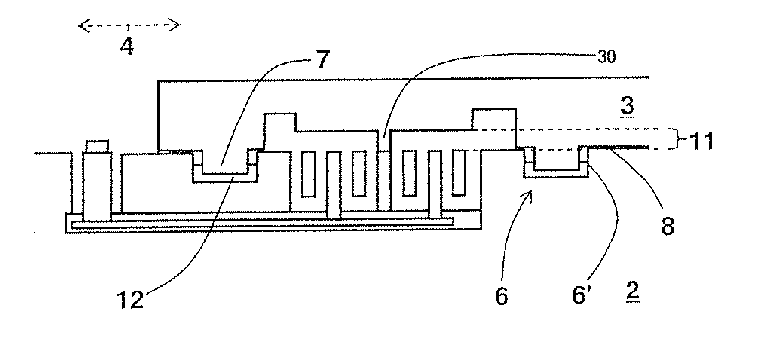
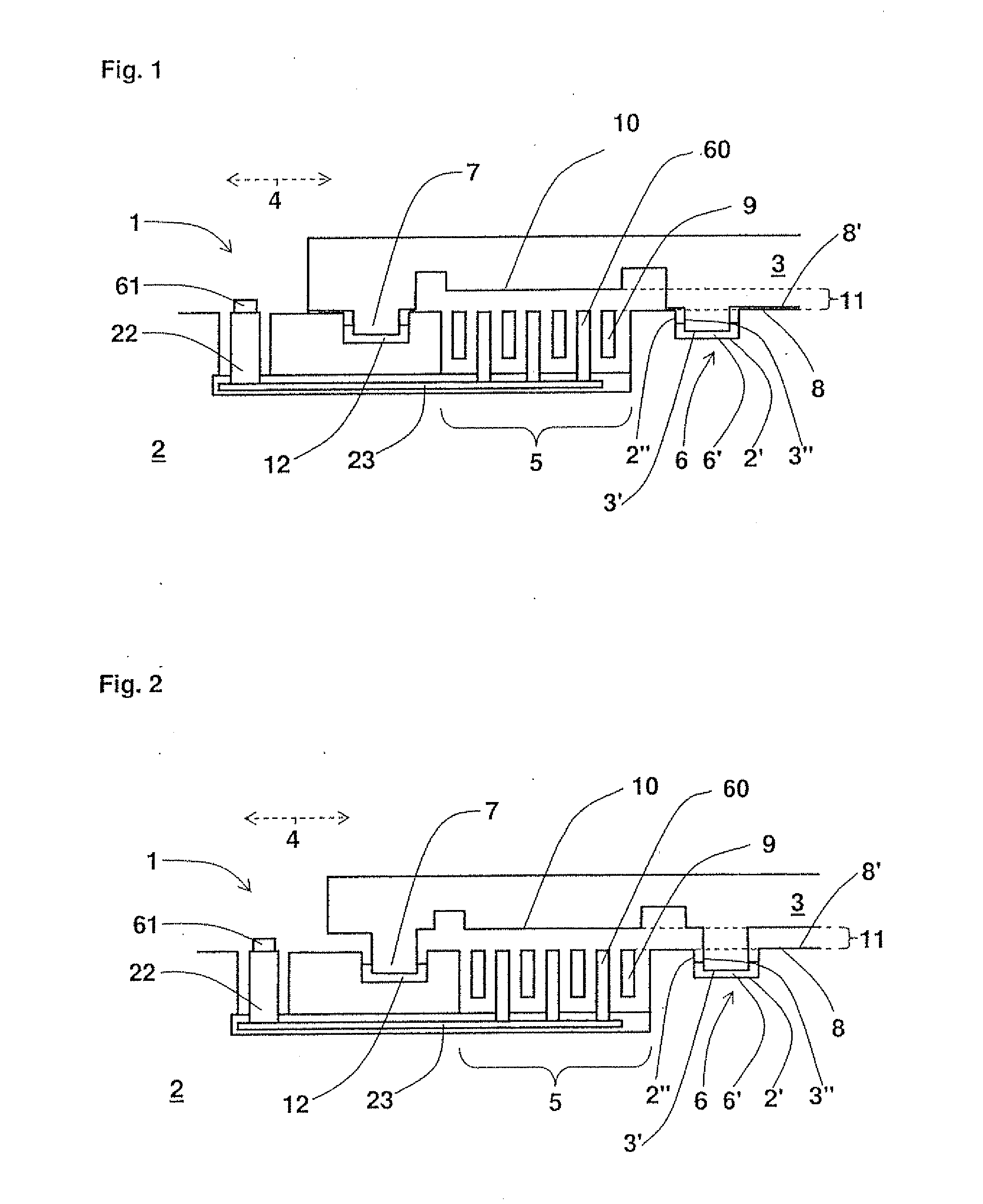
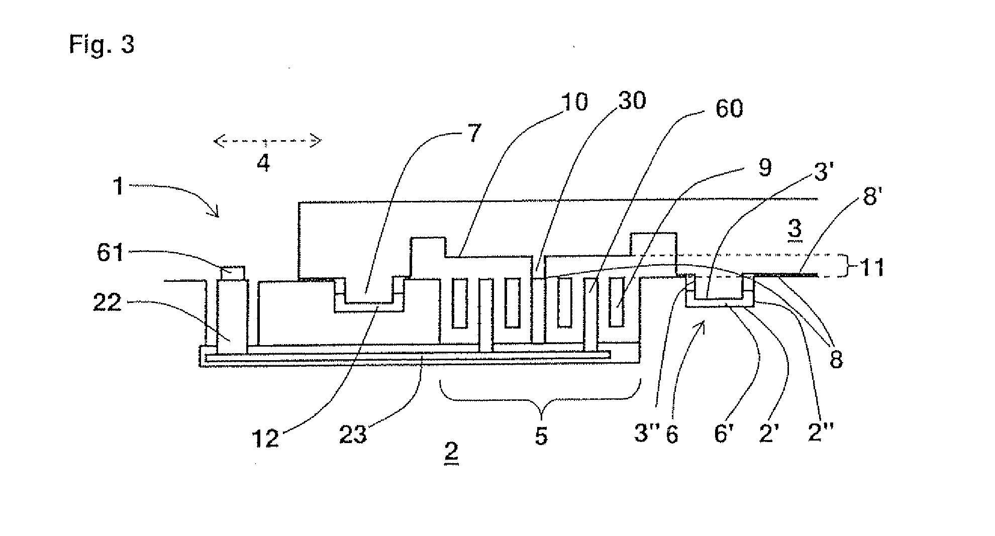
[0028]FIG. 1 shows a schematic side view of a first exemplary specific embodiment of micromechanical component 1 according to the present invention; micromechanical component 1 has a functional layer 2 and a cap wafer 3, cap wafer 3 being in parallel alignment with a first main extension plane 4 of functional layer 2, and functional layer 2 having a functional region 5; functional region 5 is at least partially surrounded by a groove 6 in functional layer 2, groove 6 being situated perpendicular to first main extension plane 4; in addition, cap wafer 3 has a stud structure 7 perpendicular to main extension plane 4, which engages with groove 6 and is mechanically fixedly connected to the groove surface in at least one subregion. Stud structure 7 and groove 6 include structural element 2″ and additional structural element 2′, as well...


PUM


Abstract

A micromechanical component, in particular a micromechanical sensor, having a first wafer and a second wafer is provided, the first wafer having at least one structural element, and the second wafer having at least one mating structural element, and, in addition, the structural element and the mating structural element are designed in such a way that a relative displacement of the first wafer relative to the second wafer parallel to a main extension plane of the first wafer essentially leads to compressive loading or tensile loading between the structural element and the mating structural element.

Description

RELATED APPLICATION INFORMATION[0001]The present application claims priority to and the benefit of German patent application no. 10 2007 044 806.8, which was filed in Germany on Sep. 20, 2007, the disclosure of which is incorporated herein by reference.FIELD OF THE INVENTION[0002]The present invention is based on a micromechanical component.BACKGROUND INFORMATION[0003]Such a micromechanical component is generally known. The printed publication DE 100 37 821 A1, for example, discusses a micromechanical component which has two functional layers lying diametrically opposed, the functional layers being operatively connected via a connecting center layer, and the functional layers additionally having a depression in the region of the operative connection. Relative displacements that occur between the functional layers parallel to their main extension plane are prevented solely by the operative connection. However, especially in the encapsulation of micromechanical components, relatively ...

Claims


Application Information

Patent Timeline
Patent Type & Authority Applications(United States)
IPC IPC(8): H01L29/06H01L21/302
CPCB81B7/0051B81C2203/019B81C2203/0118
Inventor WEBER, HERIBERTHAUSNER, RALF
Owner ROBERT BOSCH GMBH
Why Eureka
Try Eureka