
Fuel lid driving apparatus

a technology of driving apparatus and fuel lid, which is applied in the direction of roofs, locks, instruments, etc., can solve the problems of elementary errors, introduction of labor-saving infrastructure, and enormous cos

Inactive Publication Date: 2009-03-26
DENSO CORP
View PDF0 Cites 40 Cited by
  • Summary
  • Abstract
  • Description
  • Claims
  • Application Information

AI Technical Summary

Benefits of technology

[0006]In view of the above and other problems, the present disclosure, as an aspect of the invention, provides a fuel lid driving apparatus that securely prevents absence of fuel lid closure due to absentmindedness after completion of fueling at a self-serve type gas station or the like.

Problems solved by technology

Specifically, the method disclosed in the document JP-A-H08-163654 requires an auto-fueling facility in gas stations, thereby leading to an enormous cost due to an introduction of labor-saving infrastructure outside of a vehicle.
Further, fueling work in the gas station may be mainly performed by lay drivers, thereby leading to an anxiety of causing an elementary error such as absence of fuel lid closure after the completion of fueling due to absentmindedness or the like.
The technique disclosed in the above disclosures does not pay any attention to the technical background caused by a transition to the self-serve method, thereby providing no effective measure to prevent such absence of fuel lid closure after the completion of fueling.

Method used


Image

  • Fuel lid driving apparatus
  • Fuel lid driving apparatus
  • Fuel lid driving apparatus

Examples


Embodiment Construction

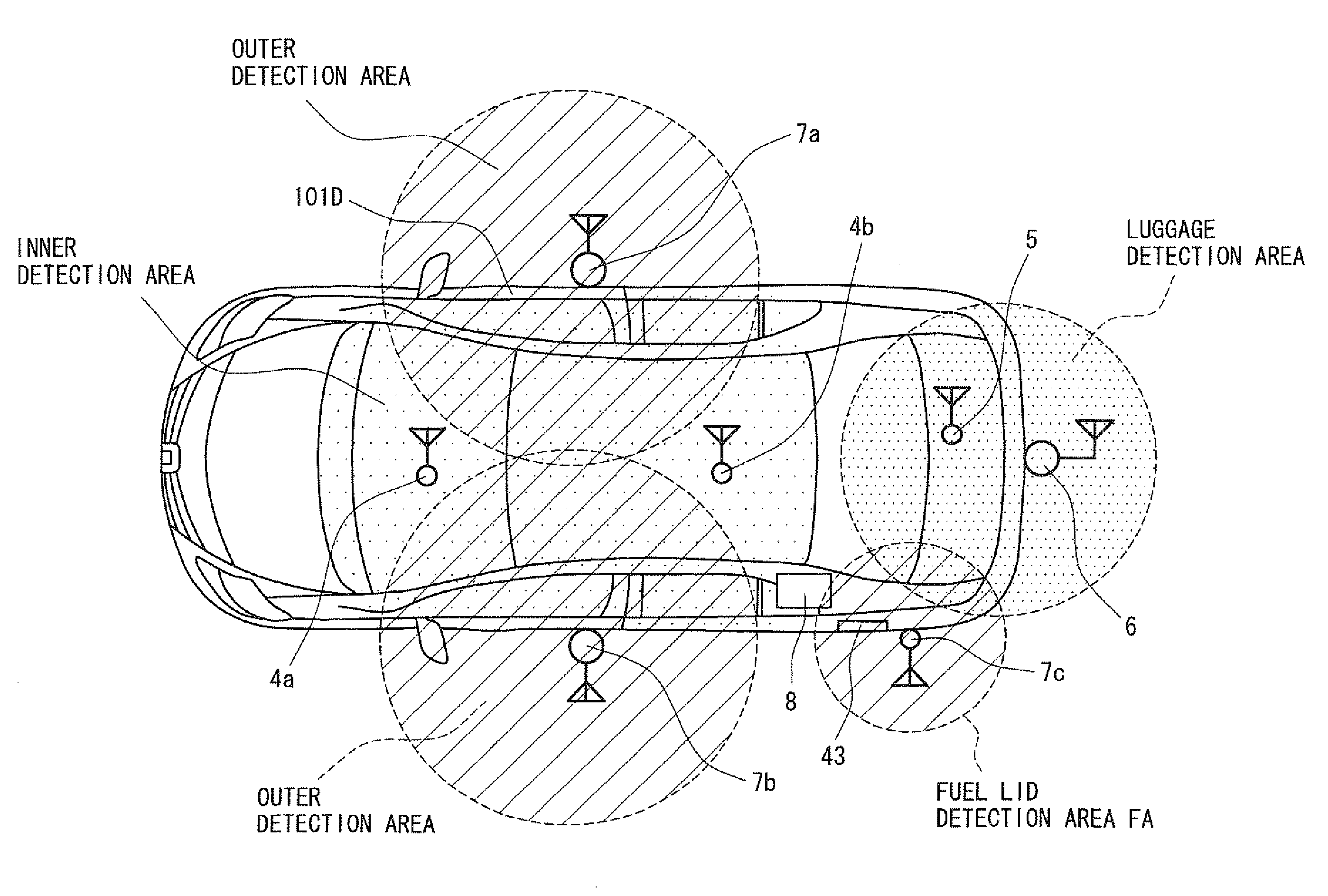
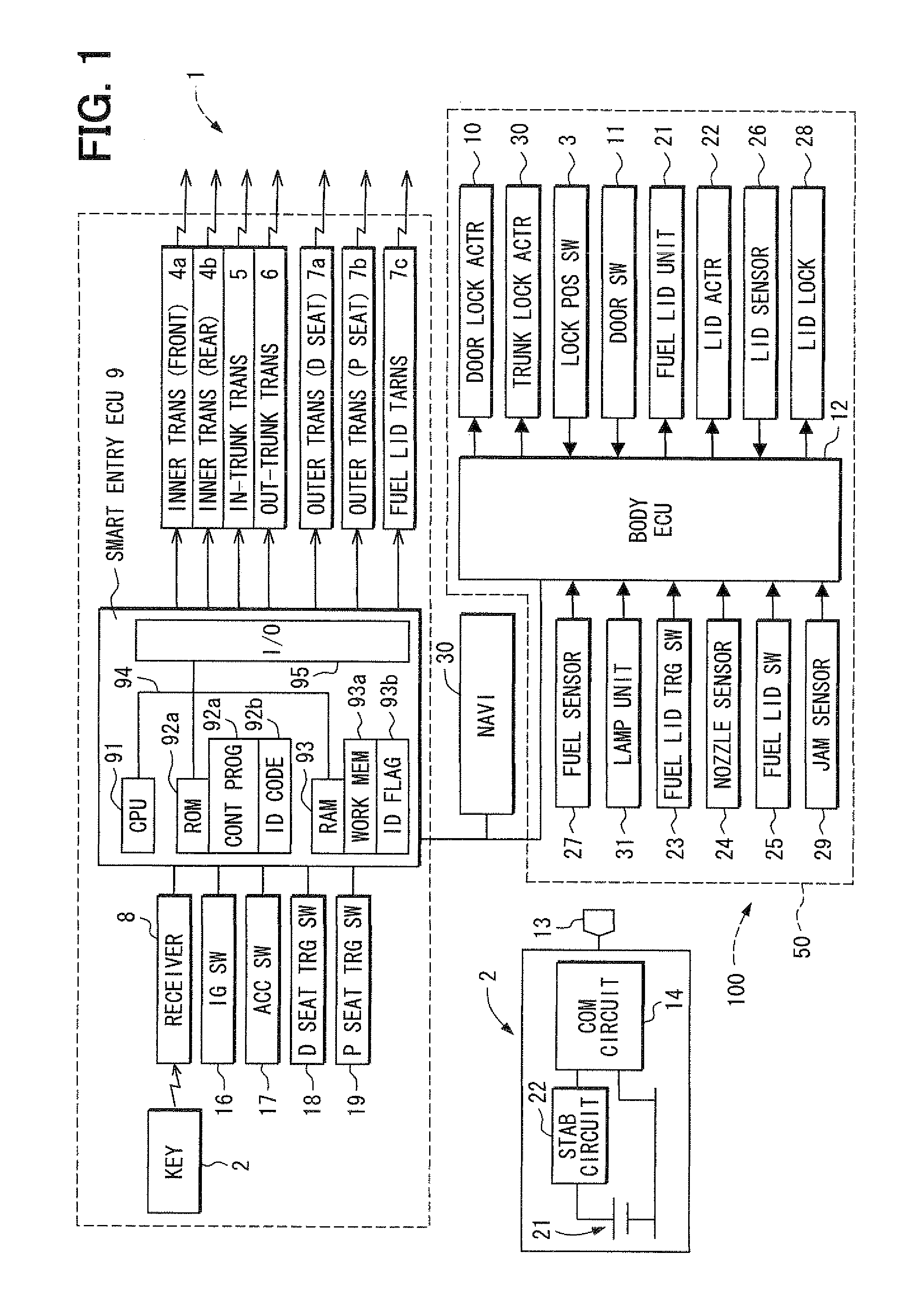
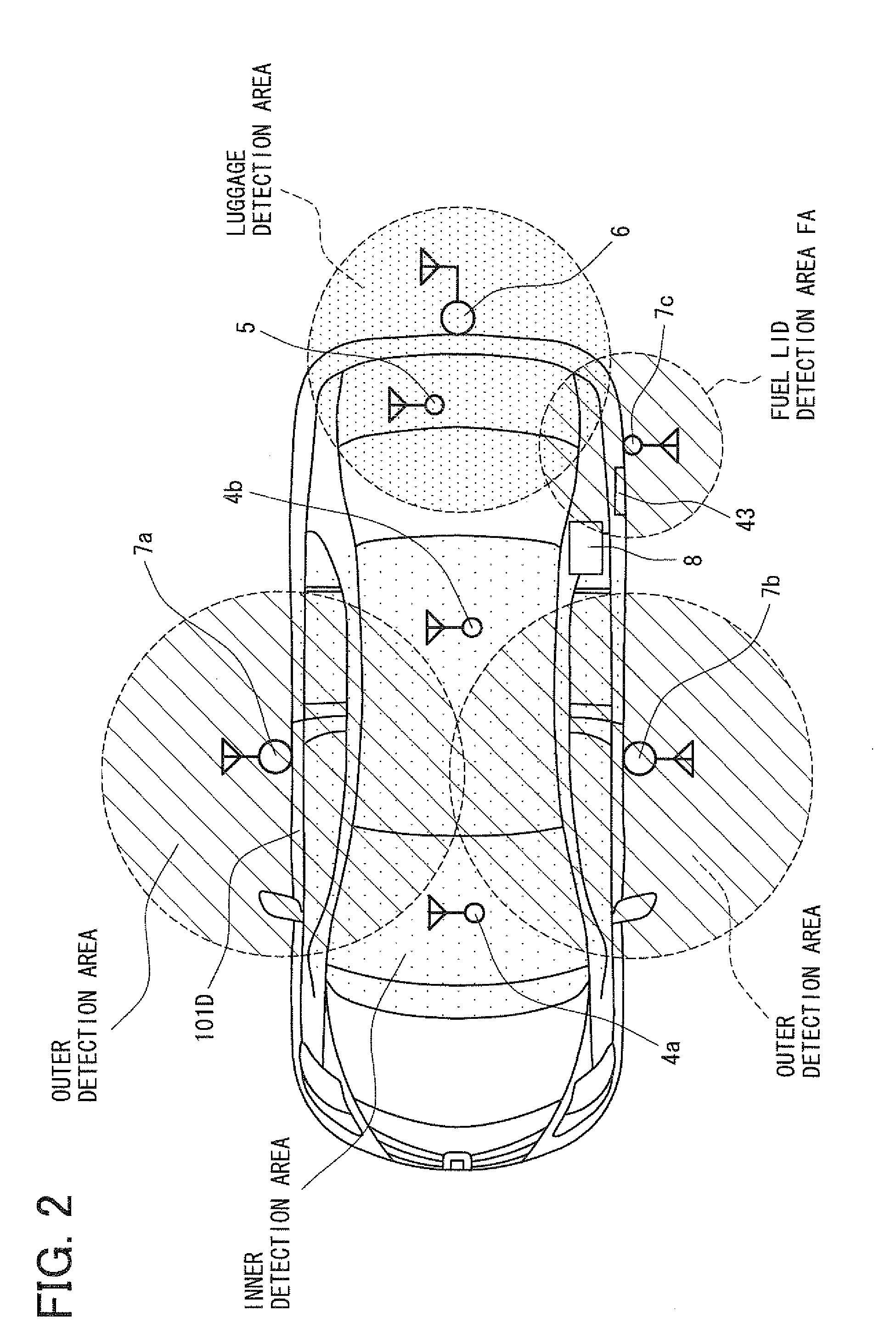
[0018]An embodiment of the present invention is explained next while referring to the drawing. FIG. 1 is a block diagram showing electric configuration of a fuel lid opening and shutting mechanism 100 in one embodiment of the present invention. In the essential part of the fuel lid opening and shutting mechanism 100, it is mainly constituted from a so-called smart entry system (a wireless lock system) 1 connected through a communication line and a body control unit 50. The subject of controlling of the smart entry system 1 is a smart entry ECU 9, and the other parts such as a receiver 8 (authentication information reception means), in-vehicle transmitters 4a, 4b, a in-trunk transmitter 5, a trunk outside transmitter 6, a compartment outside D seat transmitter 7a, a compartment outside P seat transmitter 7b receiving a radio signal from a portable key 2 having wireless communication function and a fuel lid transmitter 7c are connected thereto. In addition, an IG SW (ignition switch) ...


PUM


Abstract

A fuel lid open-close mechanism includes a fuel lid open sensor for detecting an opening of a fuel lid, and the fuel lid is automatically closed by a fuel lid controller when the opening of the fuel lid is detected. The close operation of the fuel lid is performed when a predetermined condition of fuel lid closure absence is fulfilled. The fuel lid is closed by driving shutter members from an open position to a close position.

Description

CROSS REFERENCE TO RELATED APPLICATION[0001]The present application is based on and claims the benefit of priority of Japanese Patent Application No. 2007-246372 filed on Sep. 24, 2007, the disclosure of which is incorporated herein by reference.FIELD OF THE INVENTION[0002]The present disclosure generally relates to a fuel lid driving apparatus for use in a vehicle.BACKGROUND INFORMATION[0003]The fuel lid driving mechanism recently proposed in, for example, Japanese patent documents JP-A-H06-206457 (U.S. Pat. No. 5,533,766), JP-A-2006-299994, JP-A-2001-1770 (U.S. Pat. No. 6,234,557), and JP-A-H08-163654 drives open and close a fuel hole by operating shutter member with a motor disposed closely to the fuel hole as the alternative of a manually-driven cap or the like. Various reasons and background are stated in those documents including a prevention of hand contamination due to a handling of a lid of a tank as well as a prevention of a loss of the lid, a reduction of fueling operatio...

Claims


Application Information

Patent Timeline
IPC IPC(8): B60K15/05
CPCE05B77/48E05B81/00G08C2201/91G08C17/00E05B83/34
Inventor KATOU, KENJI
Owner DENSO CORP
Learn More