
Rechargeable battery array

a rechargeable battery and array technology, applied in the field of rechargeable batteries, can solve the problems of limited electric voltage and current delivered by a rechargeable battery, long charging time of the cells in the battery, and limited charging current flowing into the non-full cells of the full cell, etc., and achieve the effect of efficient charging

Inactive Publication Date: 2009-03-26
1POWER SOLUTIONS
View PDF10 Cites 31 Cited by
  • Summary
  • Abstract
  • Description
  • Claims
  • Application Information

AI Technical Summary

Benefits of technology

[0007]It is a primary object of this invention to overcome the shortcoming of known existing rechargeable battery array and provide an improved rechargeable battery array that can be efficiently charged despite capacity mismatch and / or failure in certain cells among the battery array.
[0008]Accordingly, aspects of the present invention have been developed with a view to substantially eliminate the drawbacks described hereinbefore and to provide low complexity architecture of a rechargeable battery array and a low-complexity method for charging a rechargeable battery array.

Problems solved by technology

The electrical voltage and current delivered by a rechargeable battery is limited by the battery chemistry.
Series cell configuration however suffers from a problem that, if one cell charges up faster than its neighbor, the full cell will limit the charging current flowing into the non-full cells.
As a result, some of the cells in the battery take a long time to charge up and the charging process is inefficient.
The overall energy storing capacity of the battery cannot be fully utilized.
The problem of unbalanced charging also gets more serious, and undesirably wastes a significant portion of the battery capacity.
Apart from unbalanced charging, intrinsic faults in cells may also limit the charging current to neighbor cells.
Even if the user can tolerate a long charging time and the limited charging current may at long last charge up other cells, another problem is caused by the continuous application of charging current to those fully charged cells.
As a result, the cell life may be substantially shortened.
Such steps result in extra manufacturing costs and time.
Furthermore, the step of cell matching only improves unbalanced charging by trying to minimize the difference of charging capacity between cells, however difference in charging capacity still exists and the problem is not ultimately solved.
In addition, significant capacity mismatch still happens in spite of initial cell matching when the battery cells start to degrade after prolonged use.
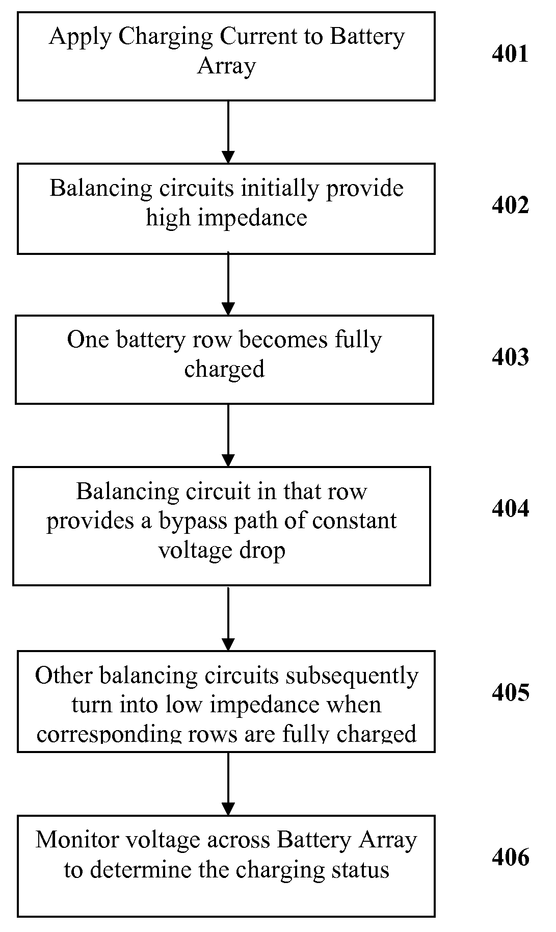
Consequently, it takes an unreasonably long time to charge up all battery rows in the battery array.
The situation gets worse when the variation of battery cell capacity increases, for example, due to battery degradation, production defects, or manufacturing process variation.
This problematic battery row gets charged up quickly and limits the charging current while the other rows still have a long way ahead to become fully charged.
Since a large current may pass through the bypass path when the balancing circuit is providing a constant voltage drop, considerable heat may be generated in the balancing circuit.

Method used


Image

  • Rechargeable battery array
  • Rechargeable battery array
  • Rechargeable battery array

Examples


Embodiment Construction

[0037]Methods and apparatus for charging rechargeable battery array are disclosed hereinafter. In the following description, numerous specific details, including battery array size, charging voltages, currents, and the like are set forth. However, from this disclosure, it will be apparent to those skilled in the art that modifications and / or substitutions may be made without departing from the scope and spirit of the invention. In other circumstances, specific details may be omitted so as not to obscure the invention.

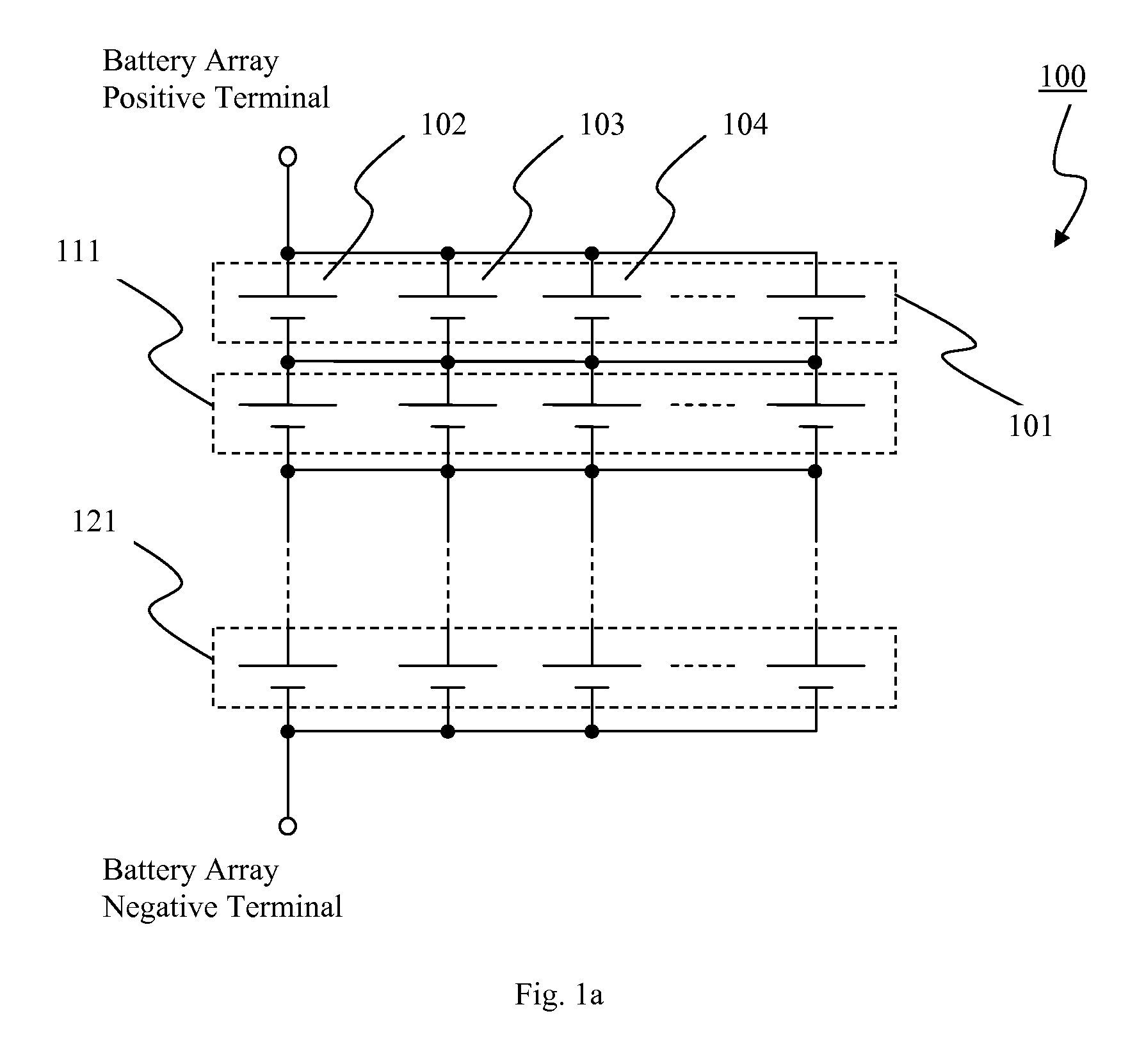
[0038]FIG. 1a illustrates a battery array 100 in conventional art composing of battery rows 101, 111, 121, etc. connected in series to provide a desired battery voltage. Each battery row comprises of battery cells 102, 103, 104, etc. connected in parallel to provide a desired battery current. Due to manufacturing process variation, production defects, or aging effect of batteries, characteristics such as energy storing capacity may vary from battery to battery.

[0039]FIG...


PUM


Abstract

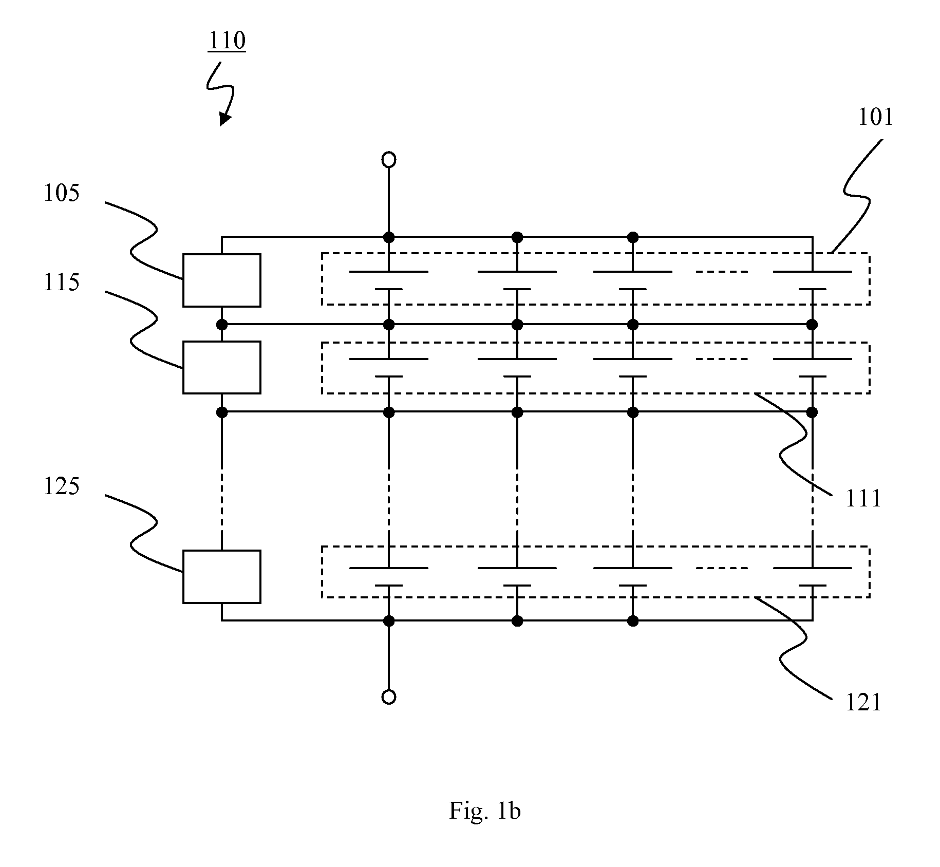
Rechargeable battery array is described. The rechargeable battery array is constructed from: a battery row 101 that includes a plurality of battery cells 102, 103 connected in parallel for supplying a larger current; and at least one balancing circuit 105 in the battery row, the balancing circuit provides a high impedance path across that battery row initially when charging process begins, and provides a path of desired constant voltage drop across that battery row when voltage across that battery row rises close to the charge termination voltage. The rechargeable battery array may further include a plurality of the battery rows 101, 111, 121 connected in series for supplying a higher voltage; and at least one balancing circuit 105 for each of the battery rows 101, 111, 121. The rechargeable battery array may also have at least one balancing circuit on each battery cell that is responsive to the voltage across that battery cell. The rechargeable battery array can be efficiently charged despite of capacity mismatch and / or failure in certain battery cells in the array.

Description

TECHNICAL FIELD[0001]The present invention relates generally to rechargeable batteries and, in particular, to methods and apparatus for charging serially connected rechargeable batteries.BACKGROUND OF INVENTION[0002]Rechargeable battery has been widely used as power source for low power consumption electronic devices such as digital camera, laptop computers, and mobile phones. The electrical voltage and current delivered by a rechargeable battery is limited by the battery chemistry. Recent development in battery technology has overcome challenges such as high energy density and long cycle time, making heavy duty applications possible. Rechargeable battery is now available for Battery Electric Vehicles (BEV), hybrid vehicles, and load leveling machines.[0003]Rechargeable battery can increase the output power by configuring its voltaic cells in parallel, series, or in both to form an array structure. A parallel configuration of cells can supply a higher current whereas a series config...

Claims


Application Information

Patent Timeline
IPC IPC(8): H02J7/00
CPCH01M10/482Y02T10/7055H02J7/0016Y02T10/70Y02E60/10
Inventor CHOI, KAI-WAI ALEXANDERCHAN, SHEUNG WA
Owner 1POWER SOLUTIONS
Learn More