Photonic bandgap fiber

a bandgap fiber and bandgap technology, applied in the field of photonic bandgap fibers, can solve the problems of limited optical waveguide distance, high transmission loss of current silica-based optical fibers, and even higher transmission loss of plastic optical fibers

Inactive Publication Date: 2009-03-26
FURUKAWA ELECTRIC CO LTD
View PDF4 Cites 11 Cited by
  • Summary
  • Abstract
  • Description
  • Claims
  • Application Information

AI Technical Summary

Benefits of technology

[0011]According to an aspect of the present invention, there is provided a photonic bandgap fiber including a hollow core formed along a center axis of the photonic bandgap fiber, through which a light propagates, and a cladding region made of silica glass. The cladding region includes air holes forming a triangular lattice arranged around the hollow core. A lattice constant Λ of the triangular lattice of the air holes is equal to or smaller than 2.1 micrometers. The confinement loss in a predetermined wavelength range including a center wavelength of a photonic bandgap is lower than scattering loss.

Problems solved by technology

However, a current silica-based optical fiber has a high transmission loss of 30 dB / km or more at, for example, a wavelength of 0.4 μm.
In addition, the plastic optical fiber has an even higher transmission loss, and therefore there is a problem of limitation in an optical waveguide distance.

Method used


Image

  • Photonic bandgap fiber
  • Photonic bandgap fiber
  • Photonic bandgap fiber

Examples


Embodiment Construction

[0020]Exemplary embodiments of a photonic bandgap fiber according to the present invention are explained in detail below. It is noted that the present invention is not limited by the embodiments. Hereinafter, the photonic bandgap fiber is referred to as a PBGF. The ultraviolet to visible range indicates a wavelength of 0.2 μm to 0.8 μm.

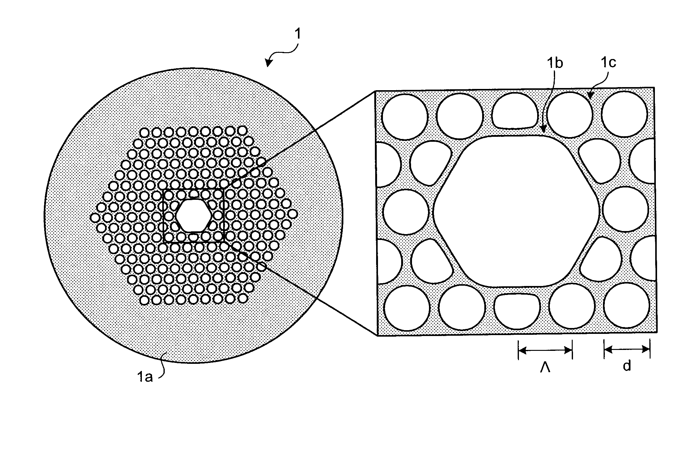
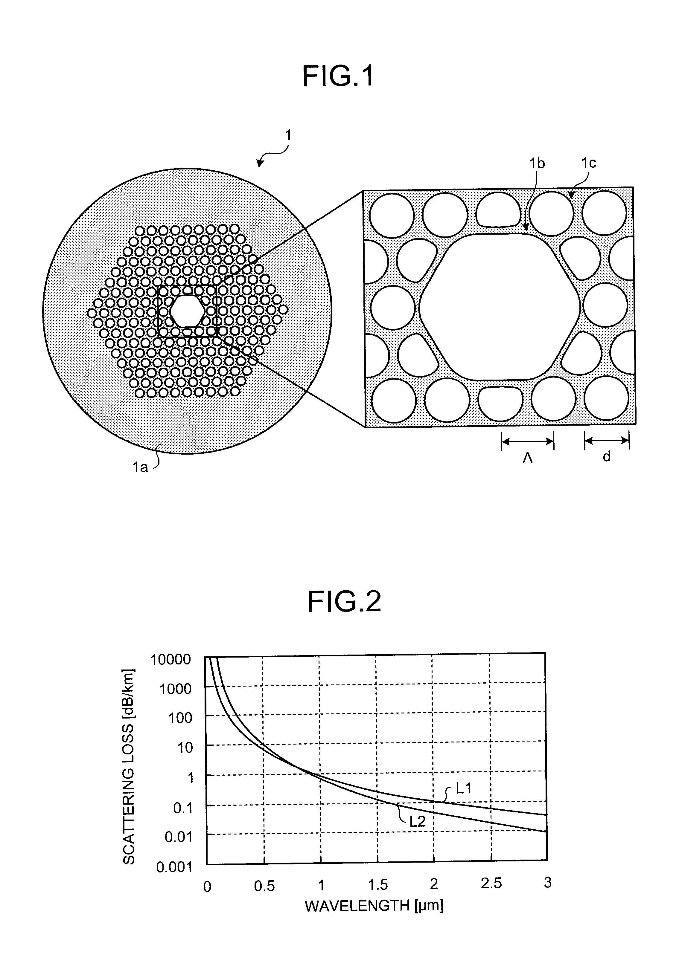
[0021]FIG. 1 is a schematic cross section and an enlarged center area of a PBGF 1 according to an embodiment of the present invention. The PBGF 1 transmits a light having a wavelength of 0.4 μm with low loss. As shown in FIG. 1, the PBGF 1 includes a hollow core 1b for propagating a light formed along the center axis of the PBGF 1 and a cladding region 1a formed around the hollow core 1b. The cladding region 1a is formed with air holes 1c periodically arranged in silica glass and the silica glass covering the periphery of the air holes 1c. The periphery of the cladding region 1a is provided with a coating (not shown) made of UV-curing resin or the lik...


PUM


Abstract

A photonic bandgap fiber includes a hollow core formed along a center axis of the photonic bandgap fiber, through which a light propagates and a cladding region made of silica glass. The cladding region includes air holes forming a triangular lattice arranged around the hollow core. A lattice constant of the triangular lattice of the air holes Λ is equal to or smaller than 2.1 μm. Confinement loss in a predetermined wavelength range including a center wavelength of a photonic bandgap is lower than scattering loss.

Description

CROSS-REFERENCE TO RELATED APPLICATIONS[0001]This application is a continuation of PCT / JP2007 / 068692 filed on Sep. 26, 2007, the entire content of which are incorporated herein by reference.BACKGROUND OF THE INVENTION[0002]1. Field of the Invention[0003]The present invention relates to a photonic bandgap fiber including a hollow core for propagating a light formed along a center axis of a cladding region and air holes periodically arranged around the hollow core.[0004]2. Description of the Related Art[0005]A light in a wavelength range from ultraviolet to visible light (ultraviolet to visible range) is used in a wide range of fields, such as medical care, biotechnology, sensing, measurement, optical recording, and material machining.[0006]From among the above fields, for example, as an application for radiation measurement, an optical waveguide for guiding a light in the ultraviolet range over a relatively long distance is used. More specifically, in facilities such as a nuclear rea...

Claims


Application Information

Patent Timeline
Patent Type & Authority Applications(United States)
IPC IPC(8): G02B6/032
CPCG02B6/02347G02B6/02328
Inventor IMAMURA, KATSUNORI
Owner FURUKAWA ELECTRIC CO LTD
Why Eureka
Try Eureka