Frequency offset monitoring device and optical coherent receiver
- Summary
- Abstract
- Description
- Claims
- Application Information
AI Technical Summary
Benefits of technology
Problems solved by technology
Method used
Image
Examples
Embodiment Construction
[0053]The main purpose of the present invention is to overcome the speed problem in the aforementioned prior art. Embodiments of the present invention will be described in detail below with reference to the accompanying drawings.
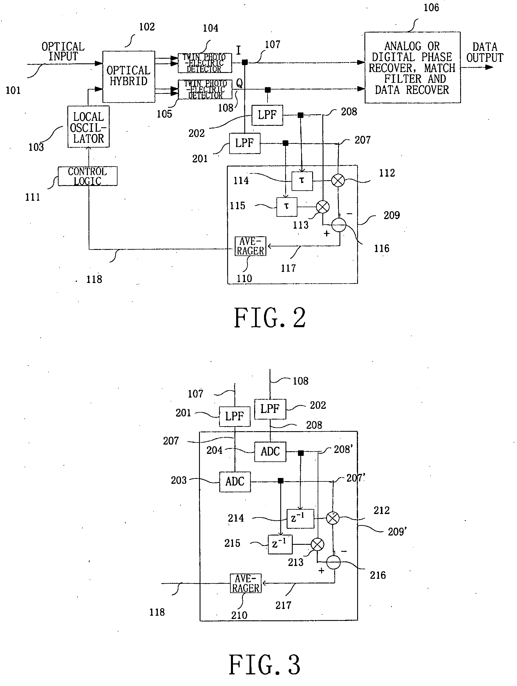
[0054]FIG. 2 shows an optical coherent receiver with analog cross product automatic frequency control according to the present invention achievable by a low speed circuit.
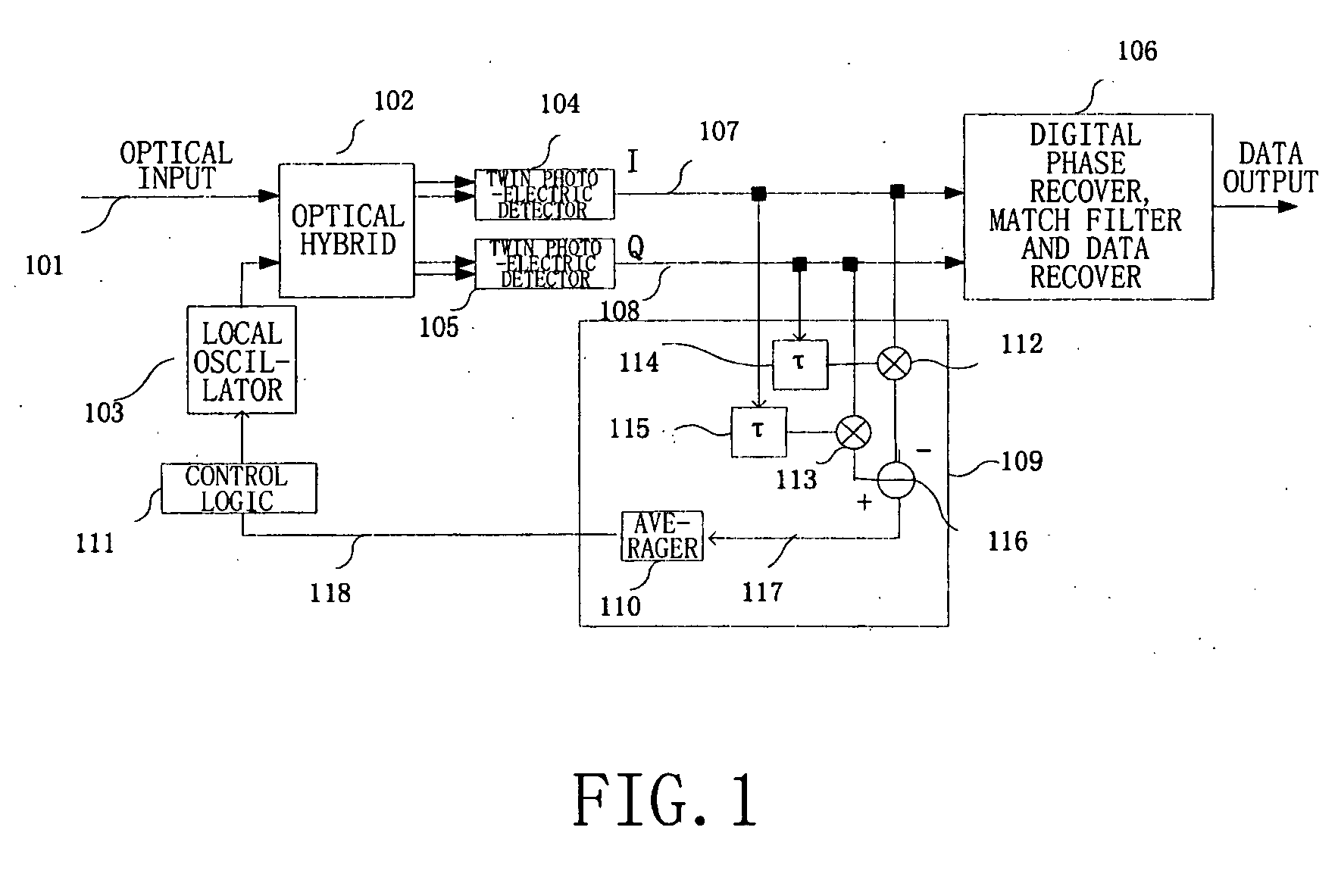
[0055]The optical coherent receiver as shown in FIG. 2 is similar in structure to that shown in FIG. 1, and the same reference numerals used in FIG. 1 are used in FIG. 2 to indicate identical or similar component parts. Besides the component parts of the structure shown in FIG. 1, in FIG. 2, there are added two low-pass filters (LPF), namely a first low-pass filter 201 and a second low pass filter 202, and the frequency offset monitor 209 calculates the self-correlation of low pass filtered signals 207 and 208, instead of the full band signals (namely the cophase signal I 107 and the quadra...
PUM
 Abstract
Description
Claims
Application Information
 - R&D
- Intellectual Property
- Life Sciences
- Materials
- Tech Scout
- Unparalleled Data Quality
- Higher Quality Content
- 60% Fewer Hallucinations
Browse by: Latest US Patents, China's latest patents, Technical Efficacy Thesaurus, Application Domain, Technology Topic, Popular Technical Reports.
© 2025 PatSnap. All rights reserved.Legal|Privacy policy|Modern Slavery Act Transparency Statement|Sitemap|About US| Contact US: help@patsnap.com


