Photolithographic method and mask devices utilized for multiple exposures in the field of a feature

Inactive Publication Date: 2009-03-26
WESTERN DIGITAL TECH INC
View PDF26 Cites 0 Cited by
  • Summary
  • Abstract
  • Description
  • Claims
  • Application Information

AI Technical Summary

Benefits of technology

[0010]It is an advantage of the photolithographic method of the present invention that the photoresist exposure time required to create a series of characters upon a device is reduced.
[0011]It is another advantage of the photolithographic method of the present invention that the exposure time for each mask that is used to create a character in a string of characters is reduced.
[0012]It is a further advanta

Problems solved by technology

However, flash (ablated particulates) on the back side of the wafer due to the laser serialization of the sliders can result in the redeposition on the front side of the ablated material from the site of the characters formed on the back of the slider.
This etching created flash can be deleterious to hard disk drive performance because it is a source of contamination that can lead to device failures, such as HDI's (head disk intera

Method used


Image

  • Photolithographic method and mask devices utilized for multiple exposures in the field of a feature
  • Photolithographic method and mask devices utilized for multiple exposures in the field of a feature
  • Photolithographic method and mask devices utilized for multiple exposures in the field of a feature

Examples


Embodiment Construction

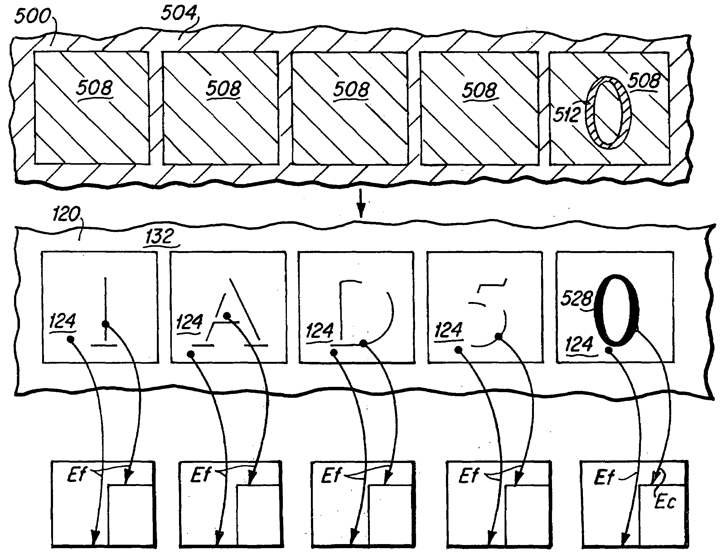
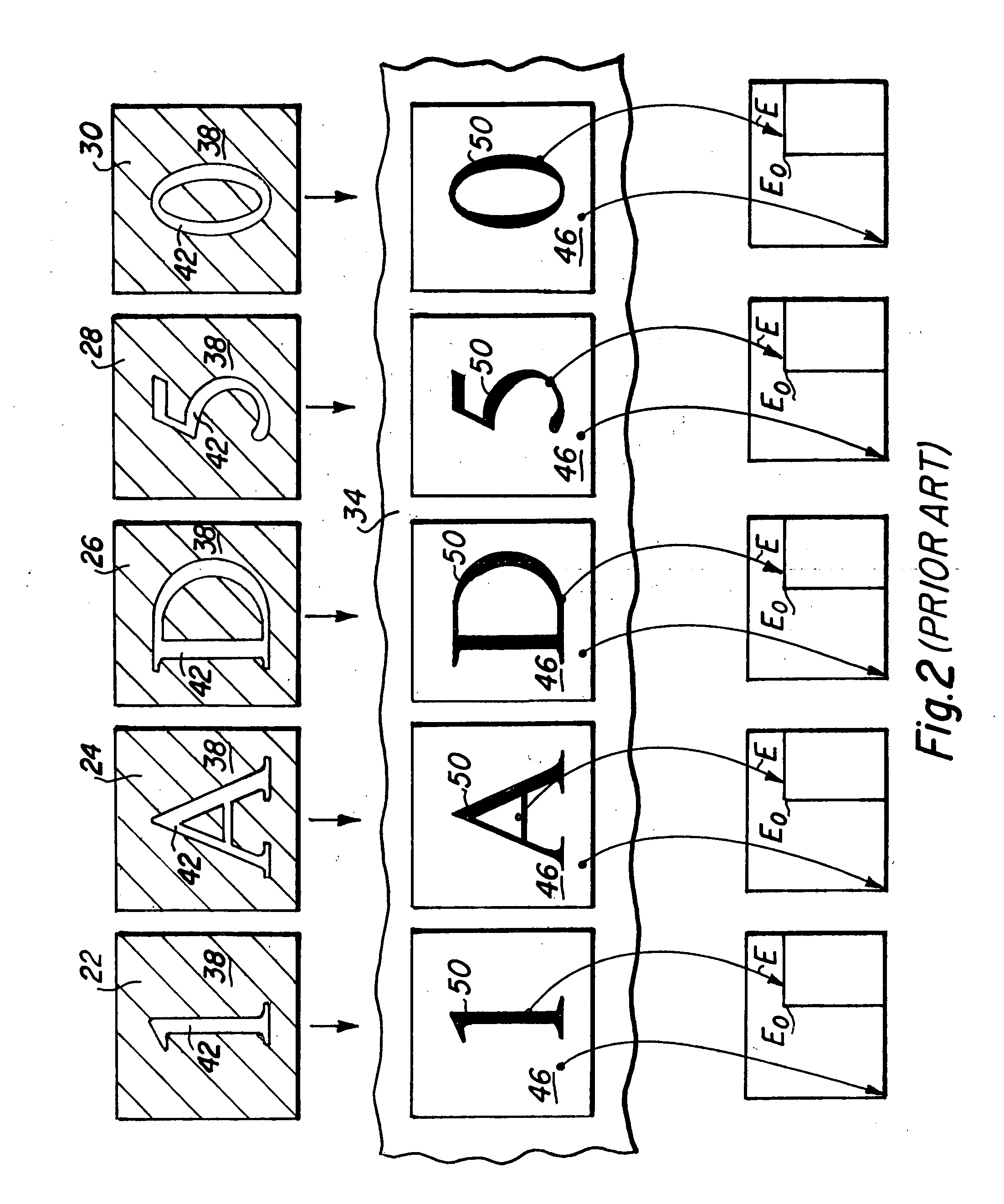
[0023]The present invention is a photolithographic process that is employed where a series of masks are sequentially utilized to expose a particular photoresist area, such as an area used in the creation of a series of characters that may comprise a device identification number. By way of example, the application of an identification number in a photoresist field, where the number involves N characters will typically utilize N masks, where a portion of each mask includes a particular character, and the masks are utilized sequentially to create a character string that comprises the identification number; thus N exposures utilizing the N masks are conducted to create the character string.

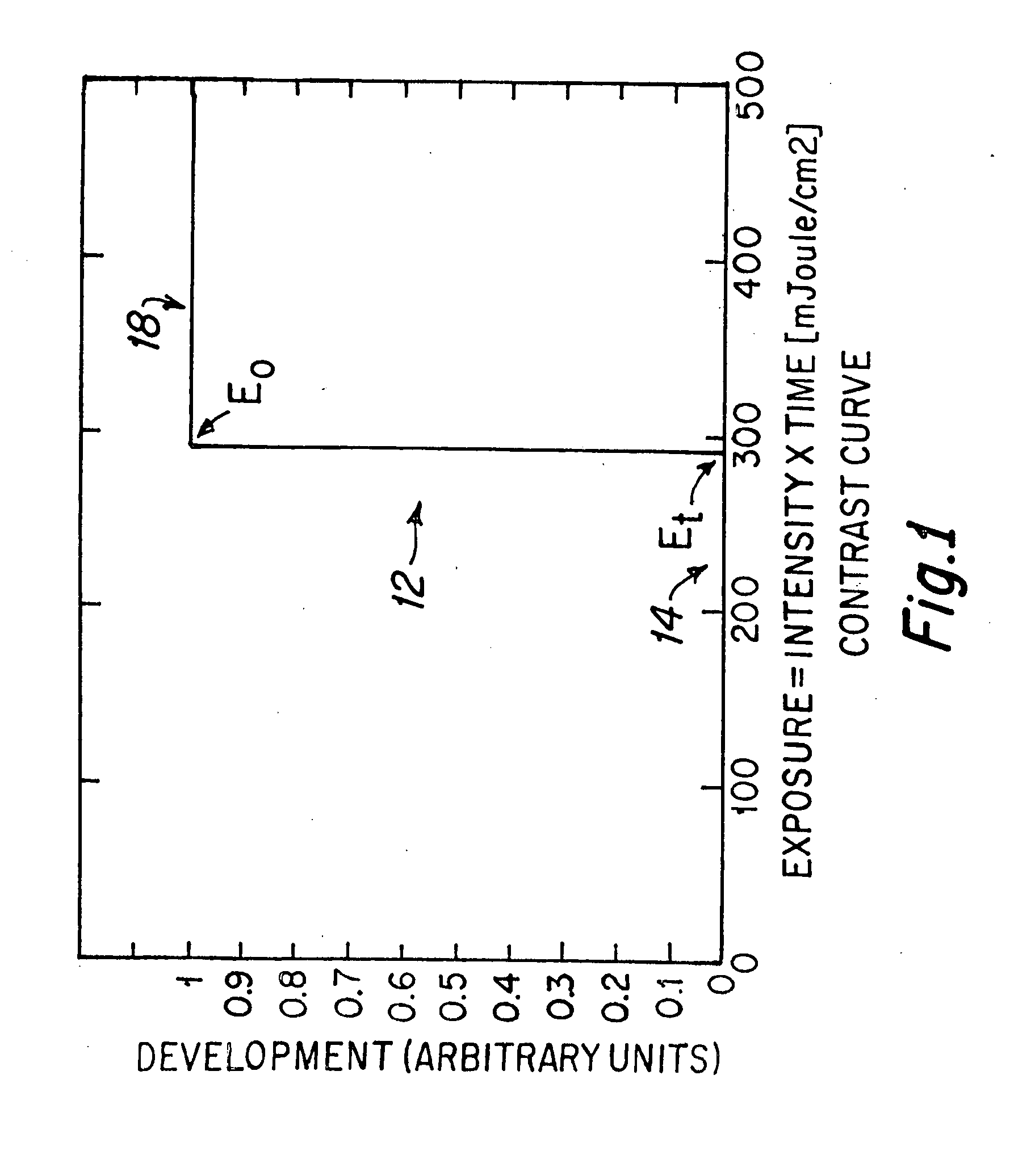
[0024]FIG. 1 depicts a typical high contrast exposure curve 12 of a typical photoresist that is suitable for use in the photolithographic method of the present invention. This contrast curve is typical of many commonly used photolithographic resists, and a resist such as 4600 series resist from Claria...


PUM


Abstract

A photolithographic method for forming a plurality of characters on a device utilizes a mask set that includes a plurality of photolithographic masks, wherein each mask includes at least one non-opaque mask character field area that surrounds a non-opaque mask character area. Photoresist is exposed to radiation energy density through the set of masks using the masks sequentially to create at least one character field area of the photoresist, and a character area of the photoresist. Ultimately, because the character areas of the photoresist are exposed to some light energy density from the non-opaque mask character field areas during each mask exposure step, the total photoresist exposure time to create the series of characters is less than that of the prior art.

Description

BACKGROUND OF THE INVENTION[0001]1. Field of the Invention[0002]The present invention relates generally to photolithographic methods and mask devices that are utilized for multiple exposures of photoresist in the field of a feature, such as the placement of an identification number on a device such as a slider for a magnetic head.[0003]2. Description of the Prior Art[0004]When devices are created on a wafer substrate, such as a slider including a magnetic head or other microelectronic devices, an identification number is typically created on each such device. In the past, the identification number has been written on the back side of the slider using a laser etching technique. However, flash (ablated particulates) on the back side of the wafer due to the laser serialization of the sliders can result in the redeposition on the front side of the ablated material from the site of the characters formed on the back of the slider. This etching created flash can be deleterious to hard disk...

Claims


Application Information

Patent Timeline
IPC IPC(8): G03F1/00G03C5/00
CPCG03F1/14G03F1/38G03F1/144G03F1/00G03F1/50
Inventor GUTBERLET, MARY KATHRYNNADER, RAMBODPARKER, MICHAEL ANDREWWERNER, DOUGLAS JOHNSON
Owner WESTERN DIGITAL TECH INC
Why Eureka
Try Eureka