Pressure detector and method of manufacturing the same

a technology of pressure detector and manufacturing method, which is applied in the direction of fluid pressure measurement, material strength using steady bending force, instruments, etc., can solve the problem of difficult control of preliminary load with a high degree of accuracy, and achieve the effect of reducing variation in preliminary load and welding strain of each pressure detector

Inactive Publication Date: 2009-04-02
DENSO CORP
View PDF10 Cites 3 Cited by
  • Summary
  • Abstract
  • Description
  • Claims
  • Application Information

AI Technical Summary

Benefits of technology

[0009]In view of the foregoing problems, it is an object of the present invention to provide a method of manufacturing a pressure detector that can reduce a variation in a preliminary load. Another object of the invention is to provide a pressure detector.
[0011]In the present manufacturing method, even when each pressure detector has different welding strain at a time when the first member and the second member are welded, the welding strain can be controlled with a high degree of accuracy by staining the one of the first member and the second member. As a result, a variation in the preliminary load of each pressure detector can be reduced.
[0013]In the present pressure detector, the preliminary load is controlled by the stain part. Thus, a variation in a welding strain of each pressure detector can be reduced and a variation in the preliminary load of each pressure detector can be reduced.

Problems solved by technology

In the above-described manufacturing method, even when the preliminary load is controlled to approach a predetermined value by monitoring the electric signal from the sensing portion, the preliminary load is difficult to be controlled with a high degree of accuracy due to a welding strain that is generated when the first member and the second member are welded.

Method used


Image

  • Pressure detector and method of manufacturing the same
  • Pressure detector and method of manufacturing the same
  • Pressure detector and method of manufacturing the same

Examples


first embodiment

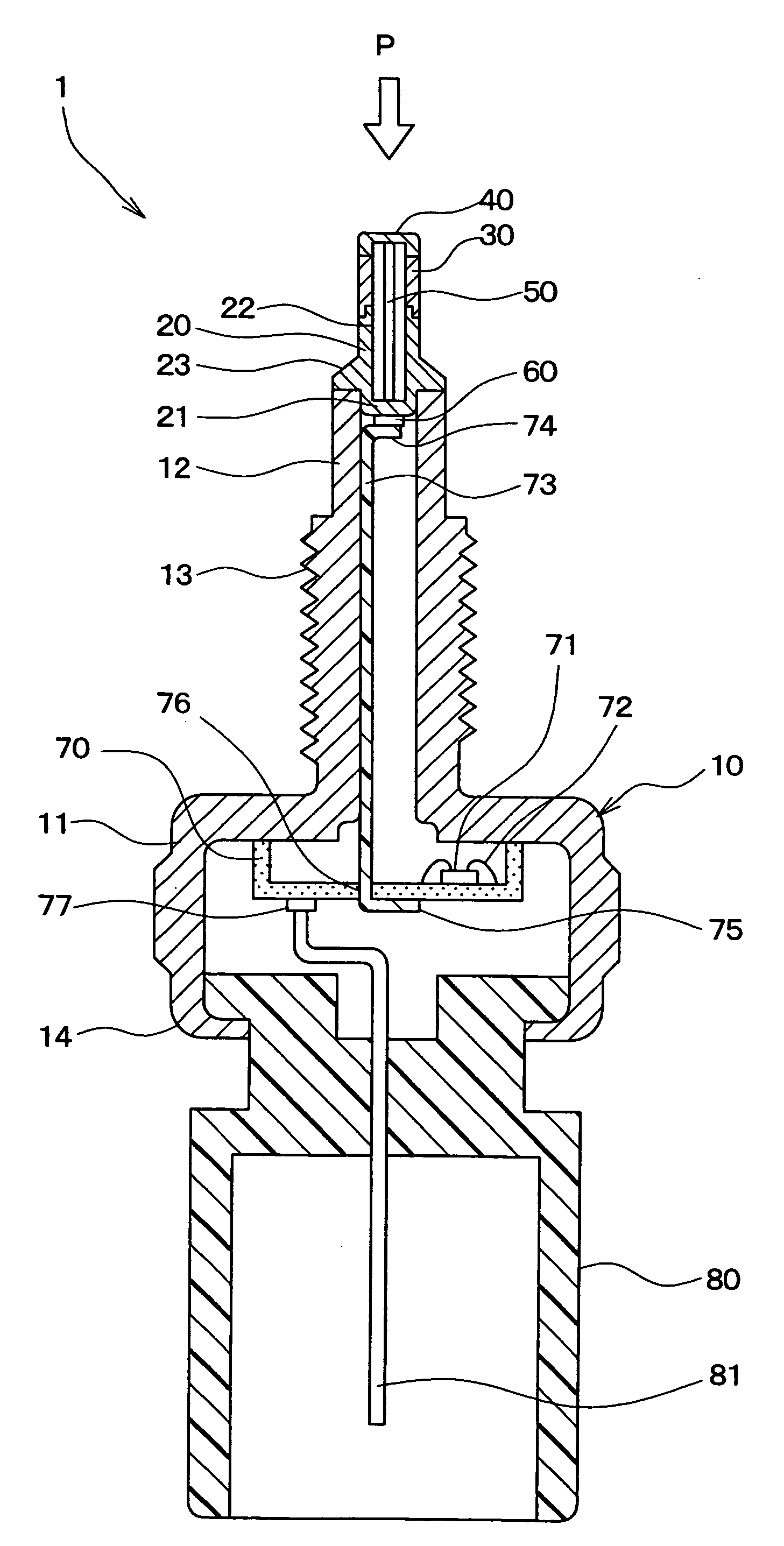
[0022]A pressure detector 1 according to a first embodiment of the invention will be described with reference to FIG. 1 and FIG. 2. The pressure detector 1 can be suitably used for a combustion pressure sensor of a vehicle, for example, and is configured to be attached to an engine head of the vehicle for detecting a pressure in a combustion chamber.

[0023]The pressure detector 1 includes a housing 10, a stem 20, a metal case 30, a pressure-receiving diaphragm 40, a rod 50, a sensor chip 60, a circuit board 70, and a connector case 80.

[0024]The housing 10 includes a body 11 having a cylindrical shape and a pipe section 12 that is longer and narrower than the body 11. The body 11 and the pipe section 12 are made of metal, for example, stainless steel. The body 11 and the pipe section 12 are formed by machining or cold forging, for example. The body 11 and the pipe section 12 may be integrally formed.

[0025]Alternatively, the body 11 and the pipe section 12 may be formed separately. In ...

second embodiment

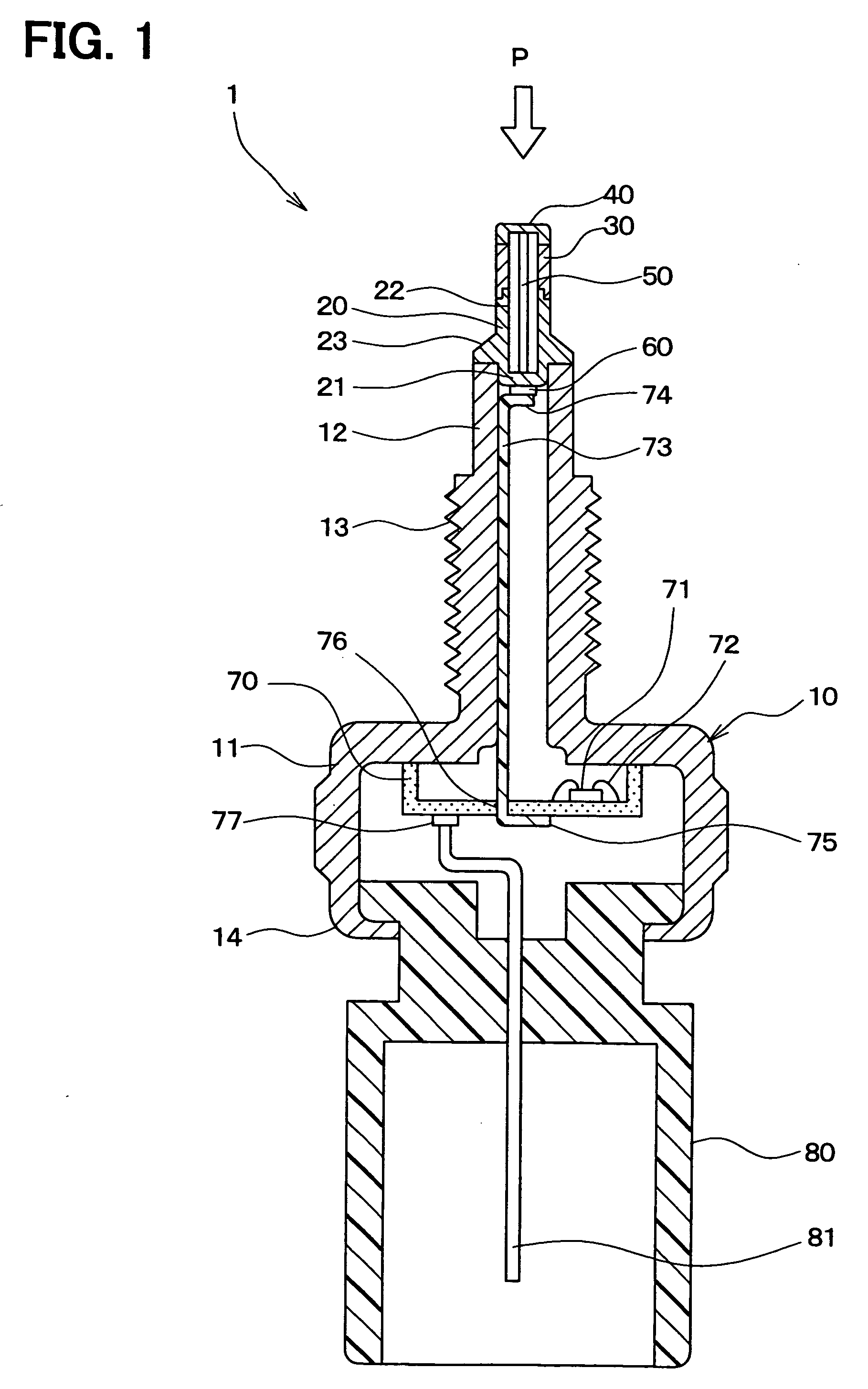
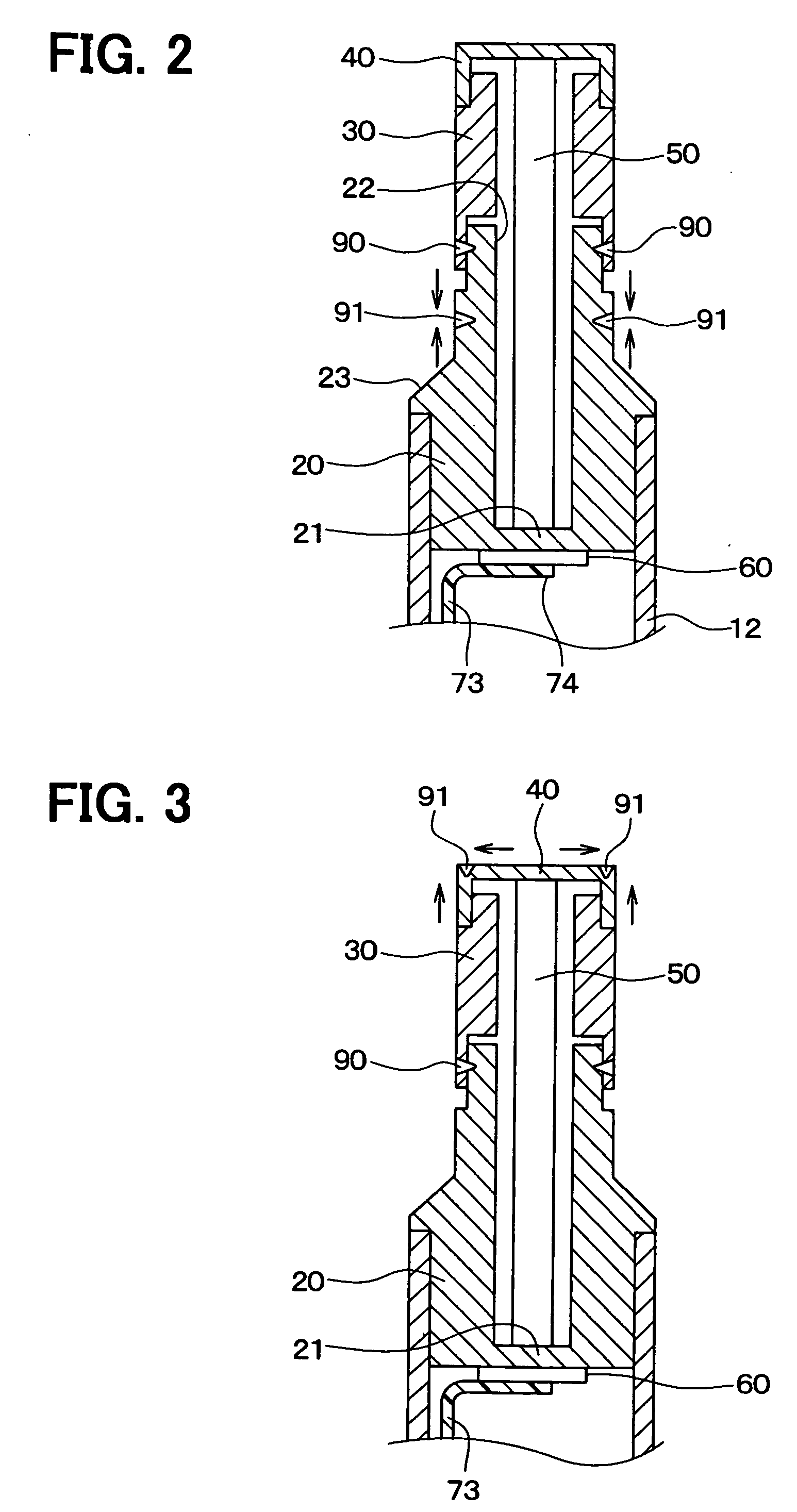
[0075]A pressure detector 1 according to a second embodiment of the invention has the second welding part 91 at the pressure-receiving diaphragm 40 as illustrated in FIG. 3.

[0076]For example, the second welding part 91 is provided at an outer peripheral portion of a surface of the pressure-receiving diaphragm 40. The second welding part 91 may have a ring shape. Alternatively, the second welding part 91 may be formed partially.

[0077]When the second welding part 91 is provided at the pressure-receiving diaphragm 40, the welding strain is generated in the longitudinal direction of the metal case 30 toward the pressure-receiving diaphragm 40 and in a radial direction of the surface of the pressure-receiving diaphragm 40 toward an outside, as illustrated by the arrows in FIG. 3. Thereby, the preliminary load applied to the sensor chip 60 can meet the predetermined value and the variation in the preliminary load of each pressure detector 1 can be reduced.

third embodiment

[0078]A pressure detector 1 according to a third embodiment of the invention has the second welding part 91 at the metal case 30 as illustrated in FIG. 4.

[0079]For example, the second welding part 91 is provided at an outer wall of the metal case 30. The second welding part 91 is provided at the whole circumference of the outer wall or a part of the outer wall.

[0080]When the second welding part 91 is provided at the metal case 30, the welding strain is generated in such a direction that the metal case 30 contracts in the longitudinal direction of the metal case 30 toward the second welding part 91. Thereby, the preliminary load applied to the sensor chip 60 can meet the predetermined value and the variation in the preliminary load of each pressure detector 1 can be reduced.


PUM

PropertyMeasurementUnit
pressureaaaaaaaaaa
thicknessaaaaaaaaaa
electricaaaaaaaaaa

Abstract

In a manufacturing method of a pressure detector, a first member that includes a sensing portion for outputting an electric signal in accordance with a pressure, a second member that includes a pressure-receiving diaphragm, and a pressure transmission member are prepared. The pressure transmission member is disposed between the sensing portion and the pressure-receiving diaphragm and the first member and the second member are welded in a state where the pressure is applied from the pressure-receiving diaphragm to the sensing portion through the pressure transmission member. One of the first member and the second member are strained so that a preliminary load, which is applied from the pressure-receiving diaphragm to the sensing portion through the pressure transmission member in a state where no external pressure is applied to the pressure-receiving diaphragm, meets a predetermined value.

Description

CROSS REFERENCE TO RELATED APPLICATIONS[0001]The present application is based on and claims priority to Japanese Patent Application No. 2007-254672 filed on Sep. 28, 2007, the contents of which are incorporated in their entirety herein by reference.BACKGROUND OF THE INVENTION[0002]1. Field of the Invention[0003]The present invention relates to a pressure detector and a method of manufacturing the pressure detector.[0004]2. Description of the Related Art[0005]As an example of the prior art, US 2006 / 0162141A (corresponding to JP-A-2006-208043) discloses a method of manufacturing a pressure detector that can be suitably used for a combustion pressure sensor. The method includes steps of: preparing a first member including a sensing portion, a second member including a pressure-receiving diaphragm, and a pressure transmission member; inserting the pressure transmission member between the first member and the second member; monitoring an electric signal from the sensing portion, the elec...

Claims


Application Information

Patent Timeline
Patent Type & Authority Applications(United States)
IPC IPC(8): G01N3/00
CPCG01L19/0645Y10T29/49002G01L23/18
Inventor MATSUI, HIROSHIGEOTSUKA, KIYOSHI
Owner DENSO CORP
Why Eureka
Try Eureka