
Method Of Accurately Metering A Gaseous Fuel That Is Injected Directly Into A Combustion Chamber Of An Internal Combustion Engine

Inactive Publication Date: 2009-04-02
WESTPORT POWER
View PDF5 Cites 33 Cited by
  • Summary
  • Abstract
  • Description
  • Claims
  • Application Information

AI Technical Summary

Benefits of technology

[0009]A method is provided for accurately metering a fuel that is injected directly into a combustion chamber of an internal combustion engine. The method comprises:
[0030]In another embodiment, the at least one sensor associated with the engine for measuring an engine parameter is a sensor with a sensing element disposed within the combustion chamber for measuring in-cylinder pressure. The other methods of determining in-cylinder pressure are preferred because, while sensors exist for measuring in-cylinder pressure directly, such instruments are much more expensive than the sensors that can be used to measure other parameters from which in-cylinder pressure can be estimated. However, future developments in instrumentation could make direct measurement of in-cylinder pressure more affordable.

Problems solved by technology

However, unlike the conventional diesel engines described above, at lower injection pressures, and since gaseous fuels are compressible fluids, the flow characteristics of gaseous fuels are different from those for liquid fuels.
The problem addressed herein, that is associated with direct injection gaseous-fueled engines, is believed to be a new problem that is not addressed by any prior art, especially since in-cylinder pressure has no significant influence on the mass flow rate of liquid fuel that injected into the combustion chamber of known diesel engines.

Method used


Image

  • Method Of Accurately Metering A Gaseous Fuel That Is Injected Directly Into A Combustion Chamber Of An Internal Combustion Engine
  • Method Of Accurately Metering A Gaseous Fuel That Is Injected Directly Into A Combustion Chamber Of An Internal Combustion Engine
  • Method Of Accurately Metering A Gaseous Fuel That Is Injected Directly Into A Combustion Chamber Of An Internal Combustion Engine

Examples


Embodiment Construction

)

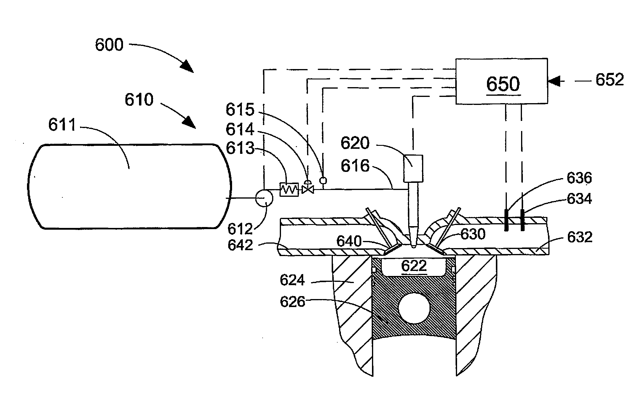
[0038]The pressure differential across the fuel injection valve is dependent upon the injection pressure and the in-cylinder pressure. In a common rail fuel injection system, the injection pressure of the gaseous fuel is the pressure of the fuel in the fuel rail, and in some engines the fuel injection pressure is variable as a function of engine operating conditions. The in-cylinder pressure is the instantaneous pressure in the combustion chamber when the fuel is being injected therein. In-cylinder pressure is dependent upon several factors. For example, the mass charge being compressed in the cylinder, which itself depends upon intake manifold air pressure, charge temperature, the volumetric efficiency of the engine at the current engine speed, the bore and stroke of the engine, and if the engine employs exhaust gas recirculation, the amount of exhaust gas that is currently being recirculated. Since the in-cylinder pressure changes throughout the engine cycle, the time at which th...


PUM


Abstract

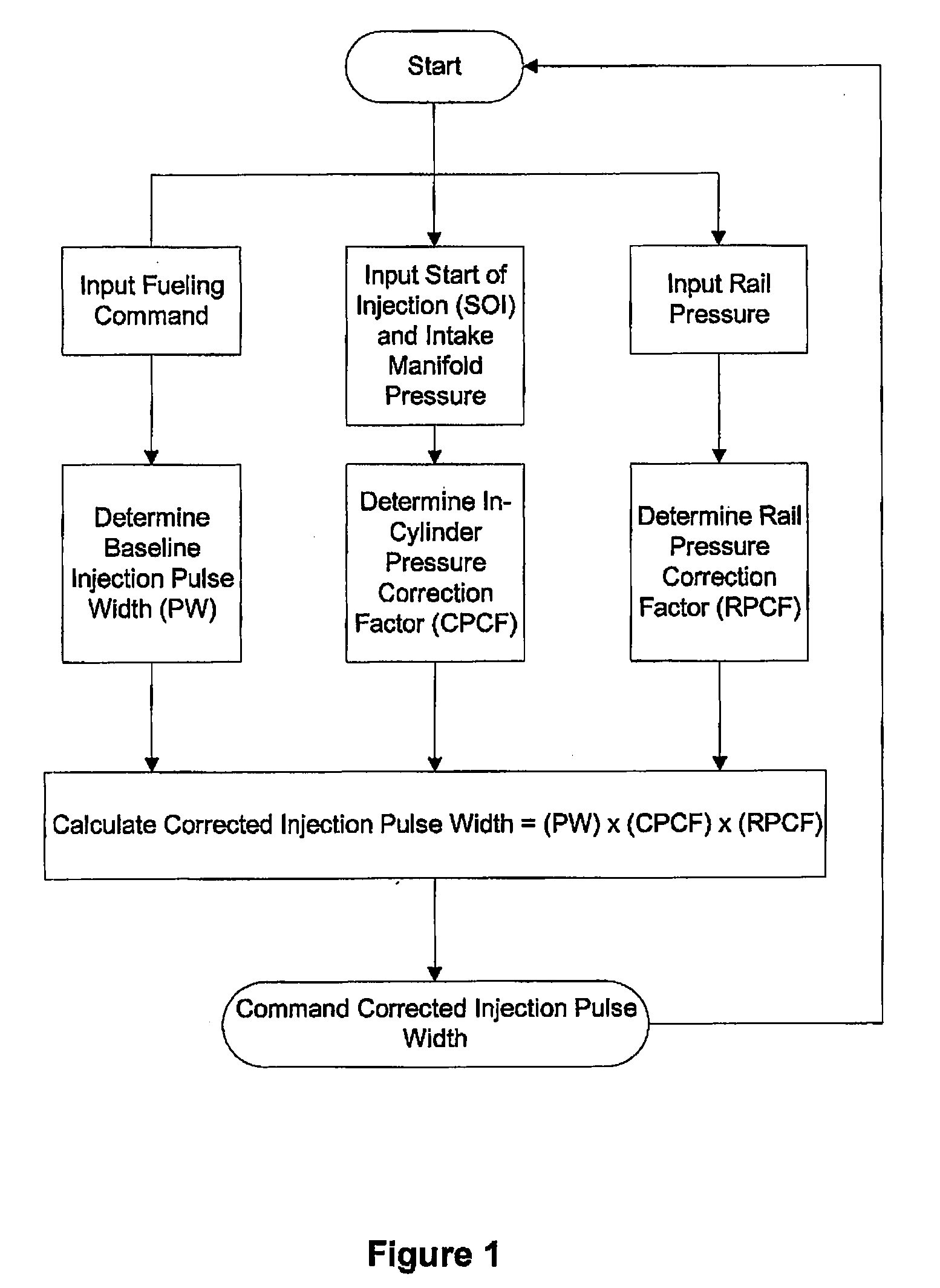
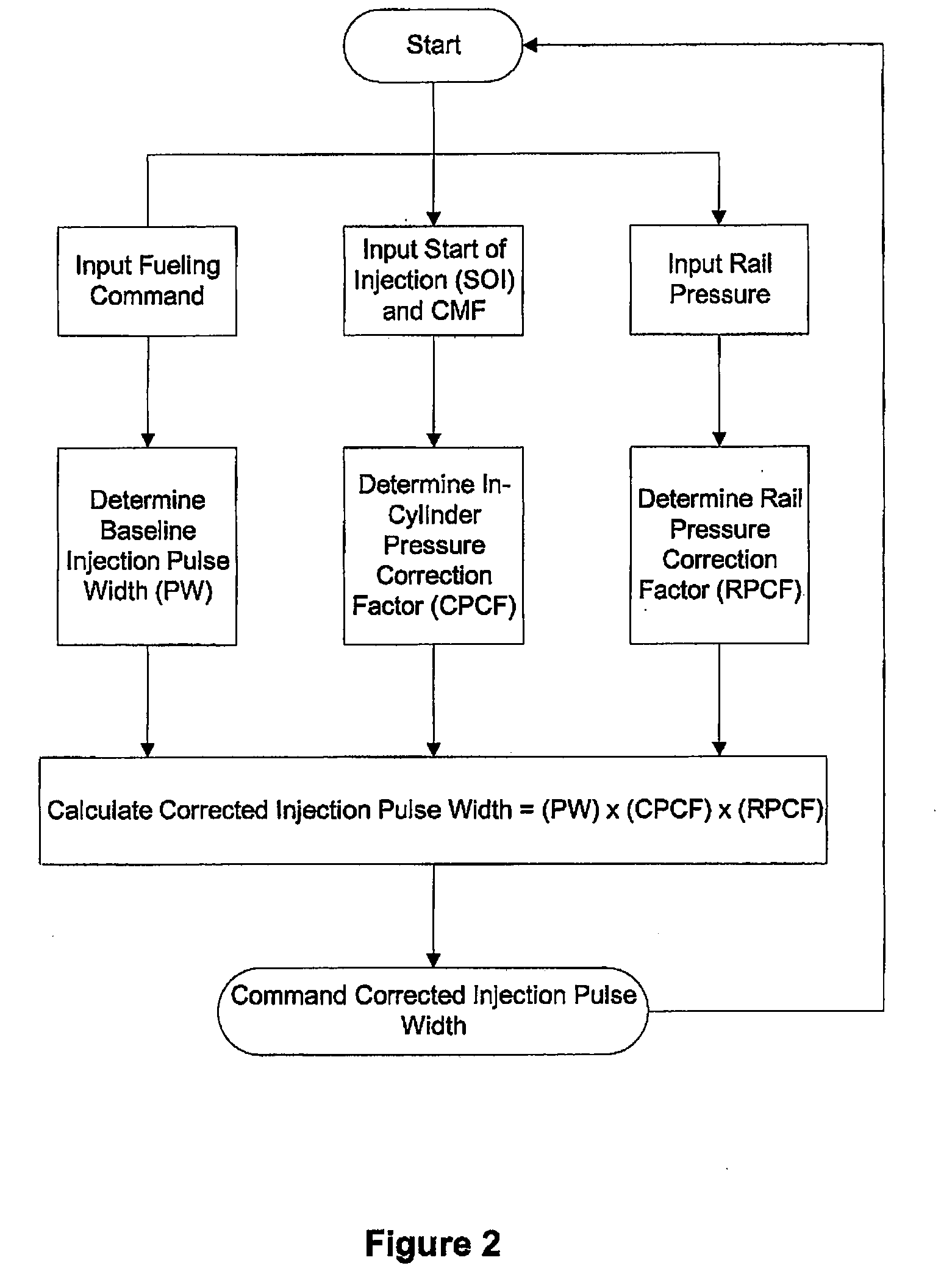
For gaseous fuels that are injected directly into a combustion chamber the mass flow rate through an injection valve can be influenced by changes in the in-cylinder pressure. A method and apparatus are provided for accurately metering a gaseous into a combustion chamber of an internal combustion engine. The method comprises inputting a fueling command; determining from said fueling command a baseline pulse width of an injection event, based upon a baseline pressure differential across a fuel injection valve; estimating the difference between said baseline pressure differential and an actual pressure differential; calculating a corrected pulse width by applying at least one correction factor to said baseline pulse width, wherein said correction factor is a function of the estimated difference between said baseline pressure differential and said actual pressure differential.

Description

CROSS-REFERENCE TO RELATED APPLICATION(S)[0001]This application is a continuation of International Application No. PCT / CA2007 / 000249, having an international filing date of Feb. 19, 2007, entitled “Method Of Accurately Metering A Gaseous Fuel That Is Injected Directly Into A Combustion Chamber Of An Internal Combustion Engine”. The '249 international application claimed priority benefits, in turn, from Canadian Patent Application No. 2,538,984 filed Mar. 10, 2006. The '249 international application is hereby incorporated by reference herein in its entirety.FIELD OF THE INVENTION[0002]The present invention relates to a method of accurately metering a gaseous fuel that is injected directly into a combustion chamber of an internal combustion engine. More specifically, the invention relates to compensating for the pressure differential between the in-cylinder pressure and the fuel supply pressure, by adjusting fuel injection pulse width to accurately meter the desired quantity of fuel t...

Claims


Application Information

Patent Timeline
IPC IPC(8): F02B43/00F02B3/00F02D41/30F02B47/08F02M25/07
CPCF02D35/023F02D35/024F02D41/0027F02D41/187F02D2041/2027F02D2041/389F02D19/027F02D2200/0602F02D2200/0604Y02T10/32F02M21/0275F02D19/024F02D2200/0406Y02T10/30
Inventor BATENBURG, GREGANCIMER, RICHARDDUNN, MARK EDWARDGOUDIE, DALE
Owner WESTPORT POWER
Learn More