Method for fabricating a microfluidic component comprising at least one microchannel filled with nanostructures

a microfluidic component and nanostructure technology, applied in microstructural technology, chemical vapor deposition coating, lamination, etc., can solve the problems of nanotubes not being able to withstand the prior cleaning steps necessary, difficult operation to perform on microscopic scale, and contaminating the environment of microcomponents. , to achieve the effect of avoiding contaminating the environment of the microcomponent, easy and inexpensiv

Inactive Publication Date: 2009-04-02
COMMISSARIAT A LENERGIE ATOMIQUE ET AUX ENERGIES ALTERNATIVES
View PDF3 Cites 26 Cited by
  • Summary
  • Abstract
  • Description
  • Claims
  • Application Information

AI Technical Summary

Benefits of technology

[0020]More particularly, the object of the invention is to provide a fabrication method whereby a microfluidic component comprising at least one microchannel homogeneously filled with nanostructures can be obtained easily and inexpensively. Advantageously the method has to be compatible with methods for producing collective components on wafers, while at the same time avoiding contaminating the environment of the microcomponent.

Problems solved by technology

However, on account of the diameter of the microchannels, filling a microchannel homogeneously with a stationary phase becomes a difficult operation to perform on a microscopic scale.
This operation does however also become difficult on this scale.
In general, nanotubes cannot withstand the prior cleaning steps necessary for performing wafer-wafer sealing, nor can they resist the high temperatures under oxidizing conditions of certain sealing techniques.
The nanotubes are further liable to pollute the surfaces performing the sealing and / or the atmosphere of the machines used during the fabrication process.
However, such a fabrication method and in particular deposition of catalyst by means of an ethanol-base solution is not practical to implement as it requires a large number of handling operations and is difficult to adapt to Microsystems.
However, formation of the carbon nanotubes proves inhomogeneous along the capillary tube.

Method used


Image

  • Method for fabricating a microfluidic component comprising at least one microchannel filled with nanostructures
  • Method for fabricating a microfluidic component comprising at least one microchannel filled with nanostructures
  • Method for fabricating a microfluidic component comprising at least one microchannel filled with nanostructures

Examples


Embodiment Construction

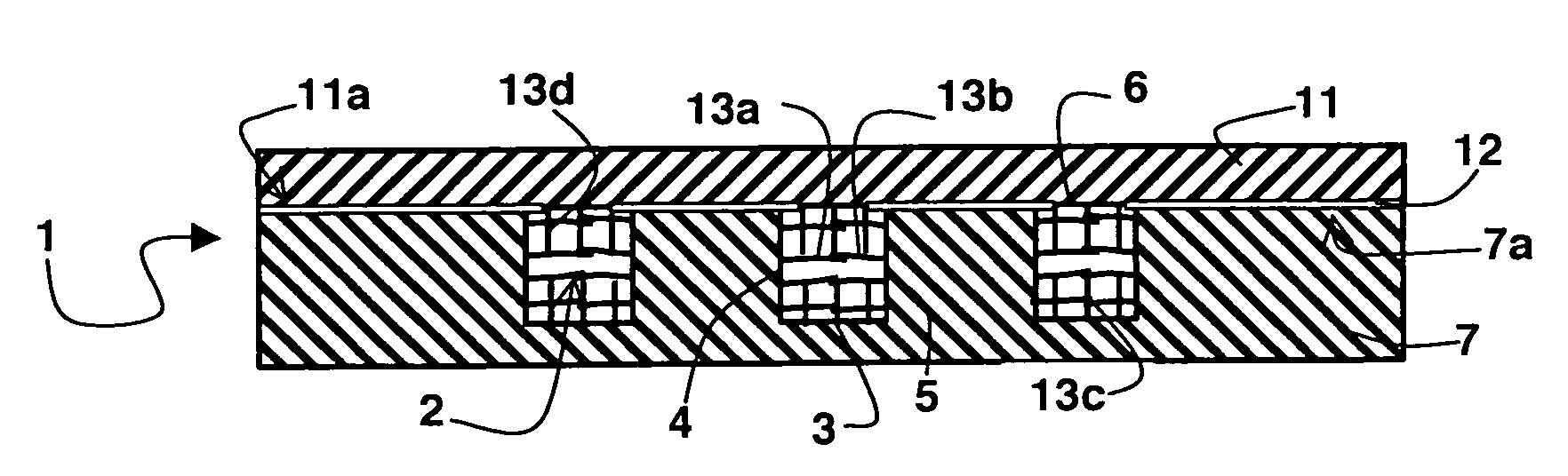
[0027]A microfluidic component, also called fluidic microsystem, comprises at least one closed microchannel enabling a fluid to flow therein. Said microchannel is delineated by bottom and top walls and two opposite side walls and is filled with nanostructures, such as nanotubes and in particular carbon nanotubes.

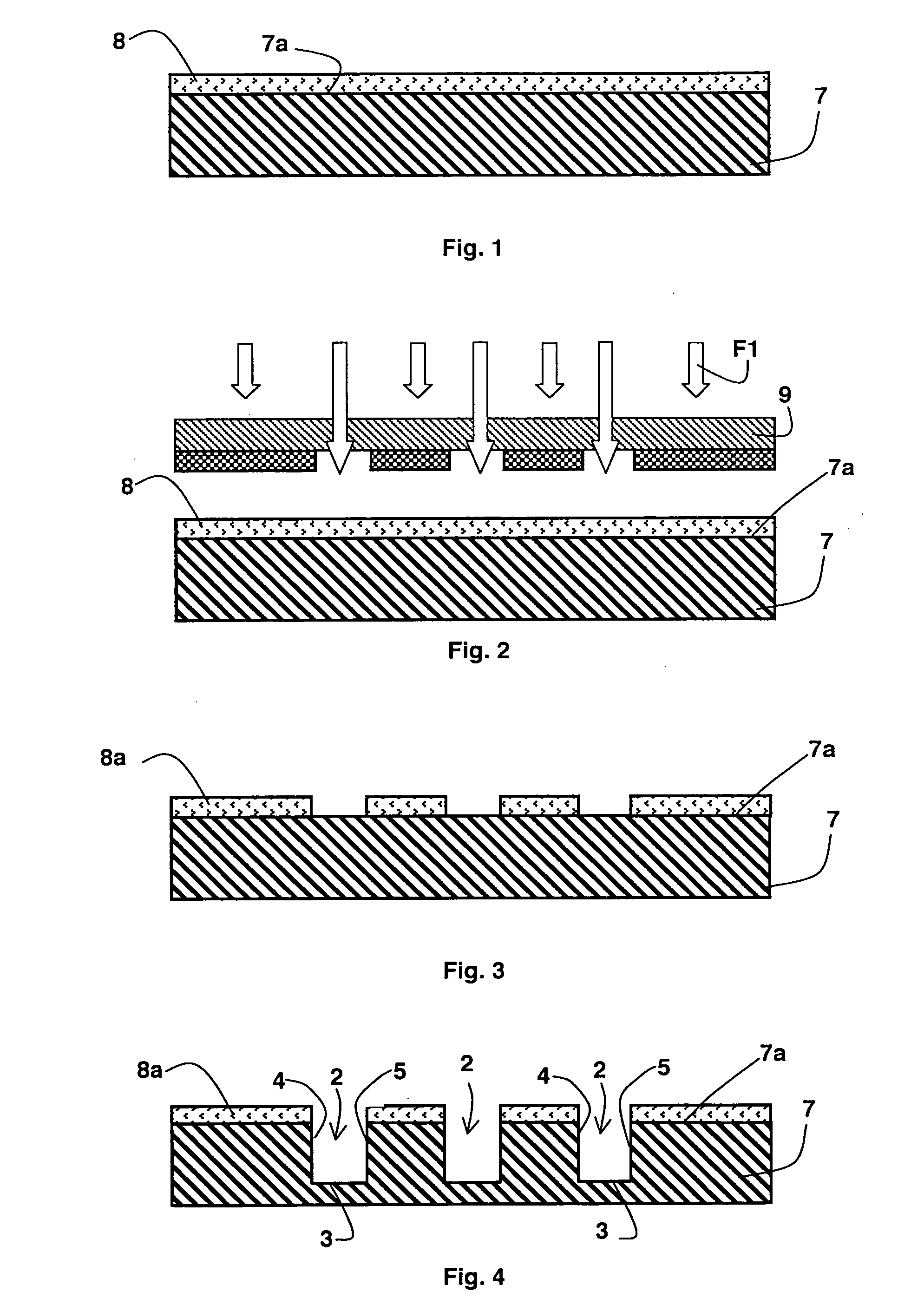
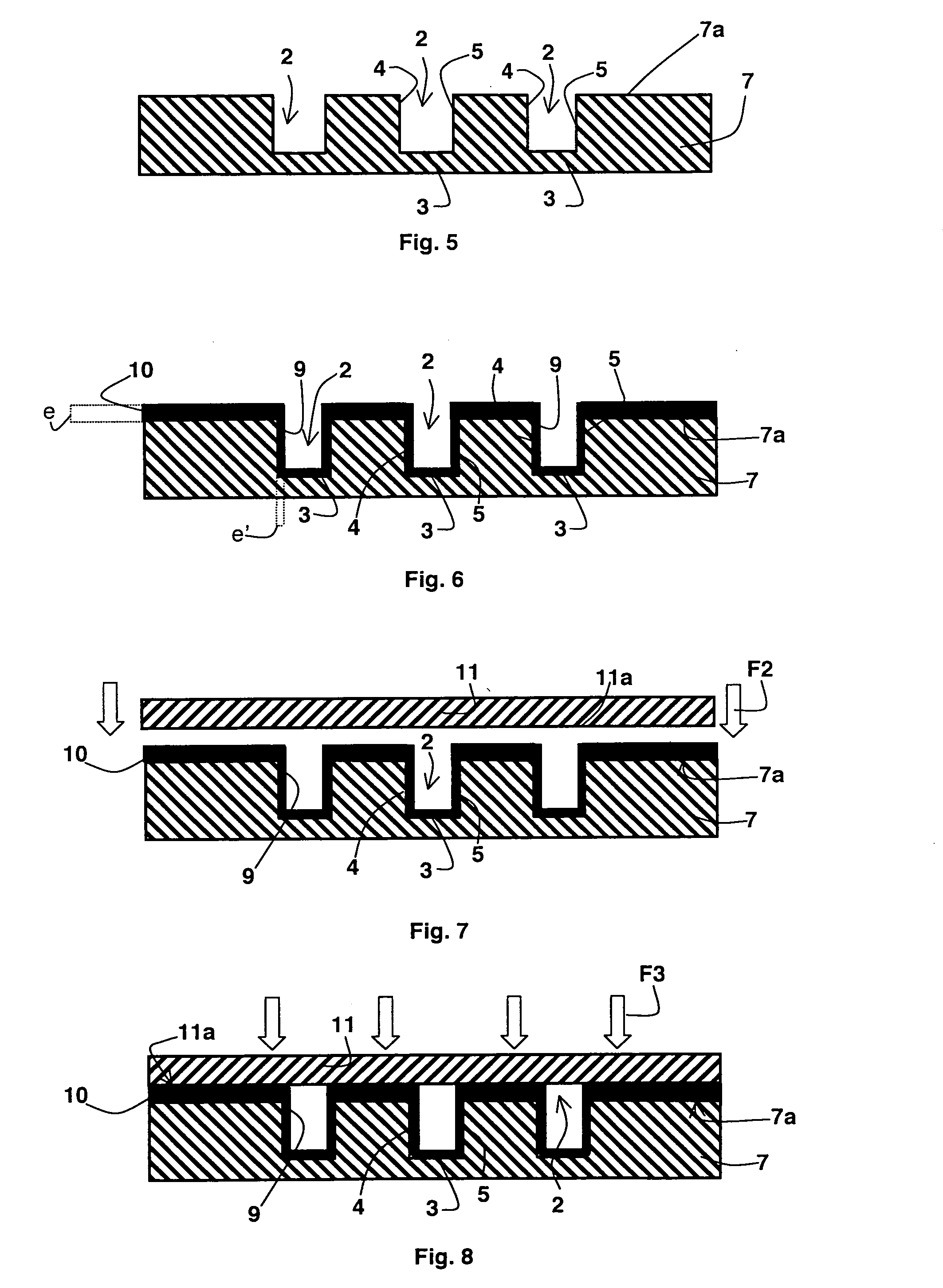
[0028]The component is achieved by previously forming the bottom wall and the opposite two side walls of said microchannel in a surface of a substrate, for example made of silicon, silicon oxide or glass. Formation of the top wall of said microchannel is performed by fitting a cover comprising for example a material chosen from silicon, silicon oxide and glass, on said surface of the substrate and sealing the cover on said surface. Then the nanostructures filling the microchannel are formed by in situ growth from a layer of metallic catalyst deposited on the opposite side walls and on the bottom wall of said microchannel.

[0029]In this way, unlike fabrication methods describe...


PUM

PropertyMeasurementUnit
thicknessaaaaaaaaaa
thicknessaaaaaaaaaa
thicknessaaaaaaaaaa

Abstract

A microfluidic component comprises at least one closed microchannel filled with nanostructures. The microchannel is produced by previously forming an opening delineating a bottom wall and two opposite side walls of the microchannel in a surface of a substrate. The nanostructures filling said microchannel are formed by in situ growth to constitute a layer of metallic catalyst deposited on said side walls and on said wall bottom. The microchannel is closed, before the nanostructures are formed, by sealing a protective cover onto said surface of the substrate. Sealing is obtained by formation of an eutectic compound between a material of the cover and the metal of the catalyst used for in situ growth of the nanostructures and deposited on the surface of the substrate designed to come into contact with the cover.

Description

BACKGROUND OF THE INVENTION [0001]The invention relates to a method for fabricating a microfluidic component comprising at least one microchannel delineated by bottom and top walls and two opposite side walls, a method comprising:[0002]formation, in a surface of a substrate, of the bottom wall and of the two opposite side walls of said microchannel,[0003]formation of nanostructures filling said microchannel by in situ growth from a metallic catalyst layer deposited on the opposite side walls and on the bottom wall of said microchannel,[0004]and formation of the top wall of said microchannel by positioning a cover on said surface of the substrate and sealing said cover on said surface.State of the art[0005]Microfluidic components, also called fluidic microsystems, such as microreactors or microlabs known under the name of “μ-TAS” (micro Total Analysis System) or “Lab-on-a-chip”, have really taken off over the last decade for performing chemical or biological operations and / or analyse...

Claims


Application Information

Patent Timeline
Patent Type & Authority Applications(United States)
IPC IPC(8): B32B38/00
CPCB01J19/0093B81C2203/038B01J2219/00824B01J2219/00831B01J2219/00835B01J2219/00846B01J2219/00862B01J2219/00869B01J2219/00873B01L3/502707B01L3/502753B01L2300/0816B01L2300/0887B01L2300/12B81B2201/058B81B2203/0338B81C1/00206B81C2201/019B01J2219/00783
Inventor FONVERNE, AGNESDIJON, JEANRICOUL, FLORENCEROUVIERE, EMMANUELLE
Owner COMMISSARIAT A LENERGIE ATOMIQUE ET AUX ENERGIES ALTERNATIVES
Why Eureka
Try Eureka