

Temperature control apparatus, processing apparatus, and temperature control method
- Summary
- Abstract
- Description
- Claims
- Application Information
AI Technical Summary
Benefits of technology
Problems solved by technology
Method used
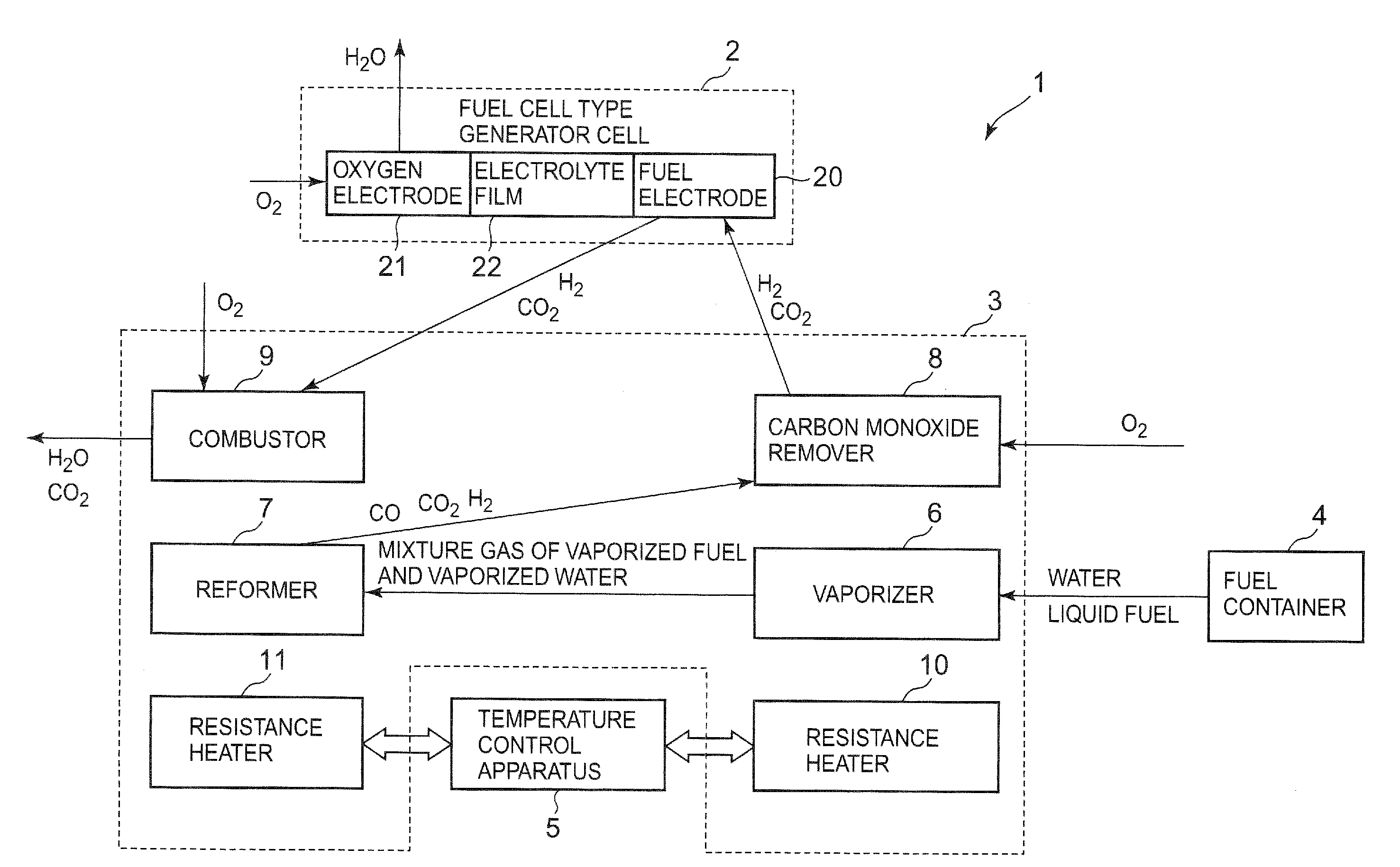
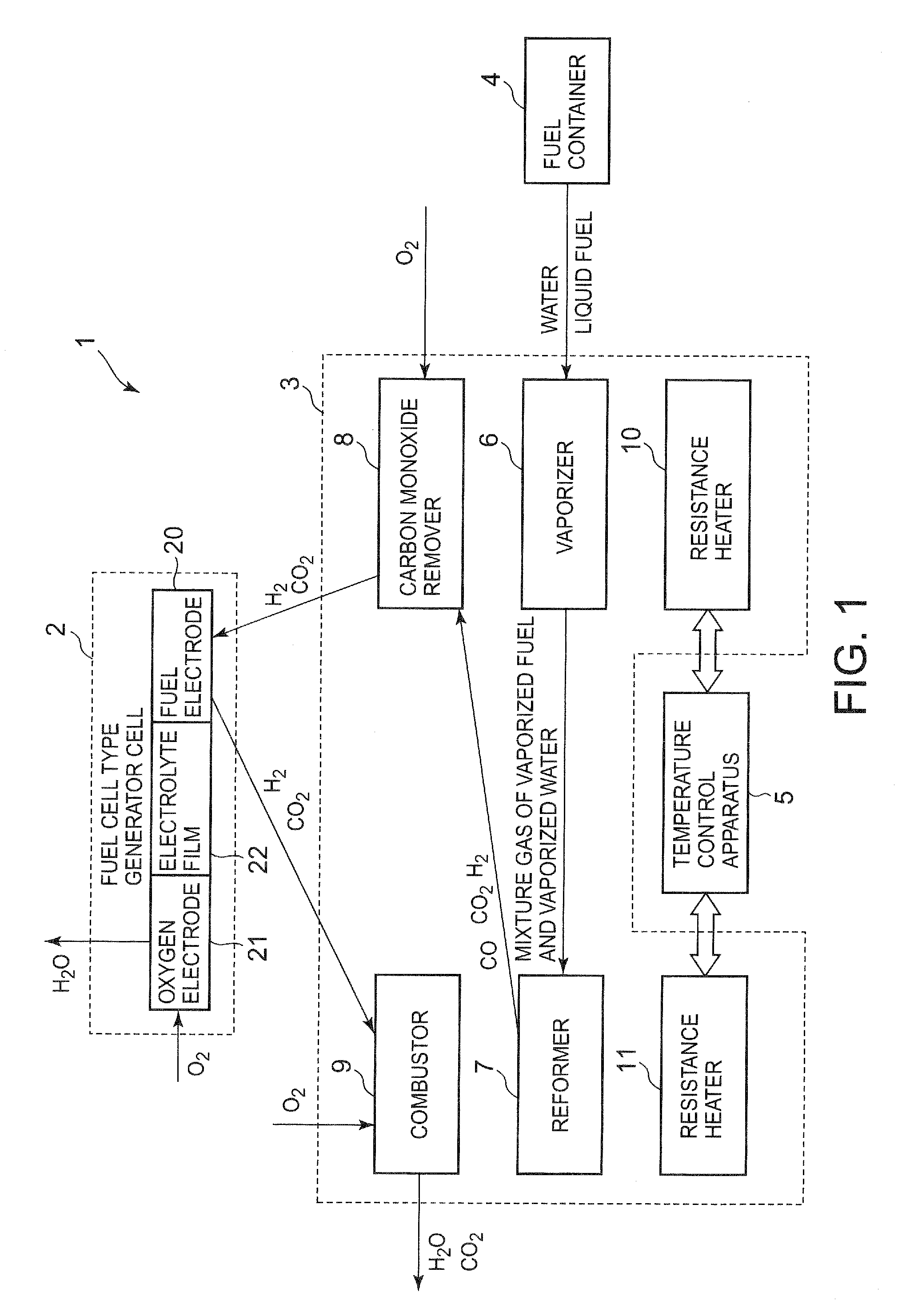
Image

Examples
first embodiment
[0041]Next, the first embodiment of the temperature control apparatus according to the present invention will be described specifically.
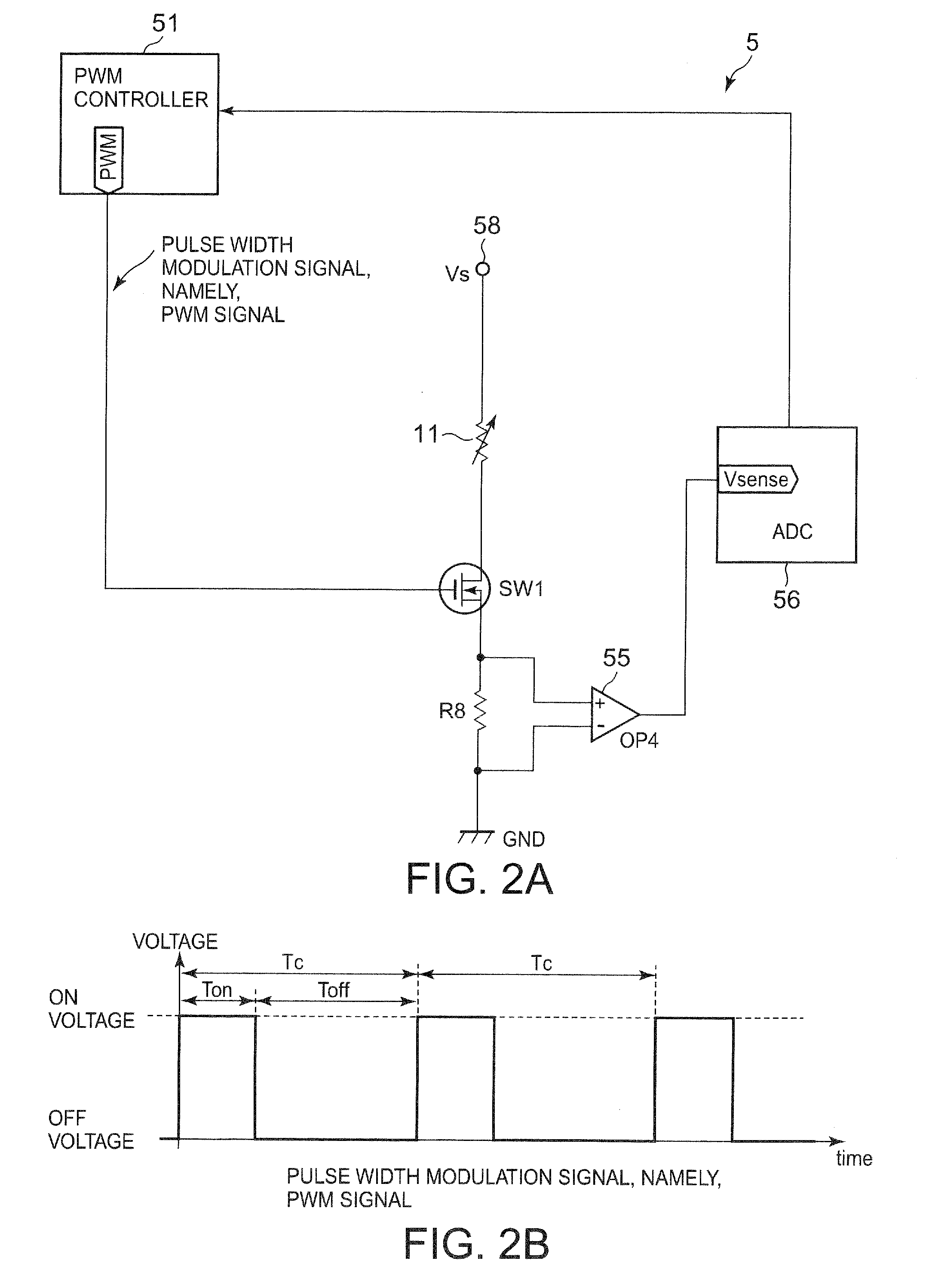
[0042]FIGS. 2A, 2B are circuit drawings showing a circuit configuration of the temperature control apparatus according to the first embodiment of the present invention, and showing a wave pattern of a control signal.
[0043]Incidentally, although FIG. 2A shows the circuit drawing of the resistance heater 11, the resistance heater 10 has same configuration as the resistance heater 11.
[0044]The temperature control apparatus 5 according to this embodiment is composed of a PWM controller 51, a differential amplifier 55 including an operational amplifier OP4 and the like, an analog to digital converter (hereinafter briefly referred to as ADC) 56, a PWM switch SW1, a fixed resistance R8, and a resistance heater 11. Incidentally, “PWM” is an abbreviation of “Pulse Width Modulation”.
[0045]The PWM controller 51 includes, for example, a central processing unit ...
second embodiment
[0089]Next, the second embodiment of the temperature control apparatus according to the present invention will be described specifically.
[0090]FIG. 4 is a circuit drawing showing a circuit configuration of the temperature control apparatus according to the second embodiment of the present invention;
[0091]As shown in FIG. 4, a temperature control apparatus 5A according to this embodiment includes a differential amplifier 54 in addition to the configuration of the temperature control apparatus 5 shown in FIG. 2.
[0092]The differential amplifier 54 outputs a signal representing a difference between the constant voltage Vs and a voltage across a connecting node of the resistance heater 11 and the PWM switch SW1, namely a voltage across the resistance heater 11, to the ADC 56. Since the differential amplifier 54 is a well-known circuit, the illustration of the components of the differential amplifier 54 such as a feedback resistance other than the operational amplifier OP3 is omitted.
[009...
third embodiment
[0099]Next, the third embodiment of the temperature control apparatus according to the present invention will be described specifically.
[0100]FIG. 5 is a circuit drawing showing a circuit configuration of the temperature control apparatus according to the third embodiment of the present invention.
[0101]As shown in FIG. 5, in a temperature control apparatus 5B according to this embodiment, a PWM switch SW2 corresponding to a switching section includes an enhancement type n-channel MOSFET 61, an enhancement type p-channel MOSFET 62, and a resistance R9.
[0102]The MOSFET 62, the fixed resistance R8 and the resistance heater 11 are connected to one another in series between the power source input terminal 58 and the ground.
[0103]Specifically, the resistance heater 11 is connected between the fixed resistance R8 and the ground, the fixed resistance R8 is connected between a drain electrode of the MOSFET 62 and the fixed resistance R8, and a source electrode of the MOSFET 62 is connected t...
PUM
 Abstract
Description
Claims
Application Information