Inking unit of a rotary press, comprising a film roller

a printing press and film roller technology, applied in the direction of rotary presses, applications, printing, etc., can solve the problems of increasing ink misting, affecting so as to achieve the effect of improving the quality of printed products and facilitating the transport of ink

Inactive Publication Date: 2009-04-09
KOENIG & BAUER AG
View PDF12 Cites 5 Cited by
  • Summary
  • Abstract
  • Description
  • Claims
  • Application Information

AI Technical Summary

Benefits of technology

[0025]In addition, and in accordance with the present invention, by mounting at least the film roller and / or the ink dividing roller and / or the ink forme rollers of the inking unit so as to allow radial movement, an improvement in the quality of the printed product produced in connection with this inking unit is possible. This quality improvement is because the contact pressure that is exerted by the respective roller can be adjusted and can be corrected as needed. With this adjustment, the transport of ink can be controlled and thereby can be optimized.

Problems solved by technology

However, the respective ink layer is necessarily relatively thick, at least on the first of the four rollers situated near the ink reservoir, due to the many gap positions between that at least first roller and the printing couple cylinder.
This results in increased ink misting in the case of a high-speed rotary printing press.
A limitation of this prior anilox roller is that a circumferential surface made of steel will create a discontinuity in ink transport after only a short period of operation, especially when used in a wet offset printing process.
This is because such a circumferential surface tends to run out of ink rapidly.

Method used


Image

  • Inking unit of a rotary press, comprising a film roller
  • Inking unit of a rotary press, comprising a film roller
  • Inking unit of a rotary press, comprising a film roller

Examples


Embodiment Construction

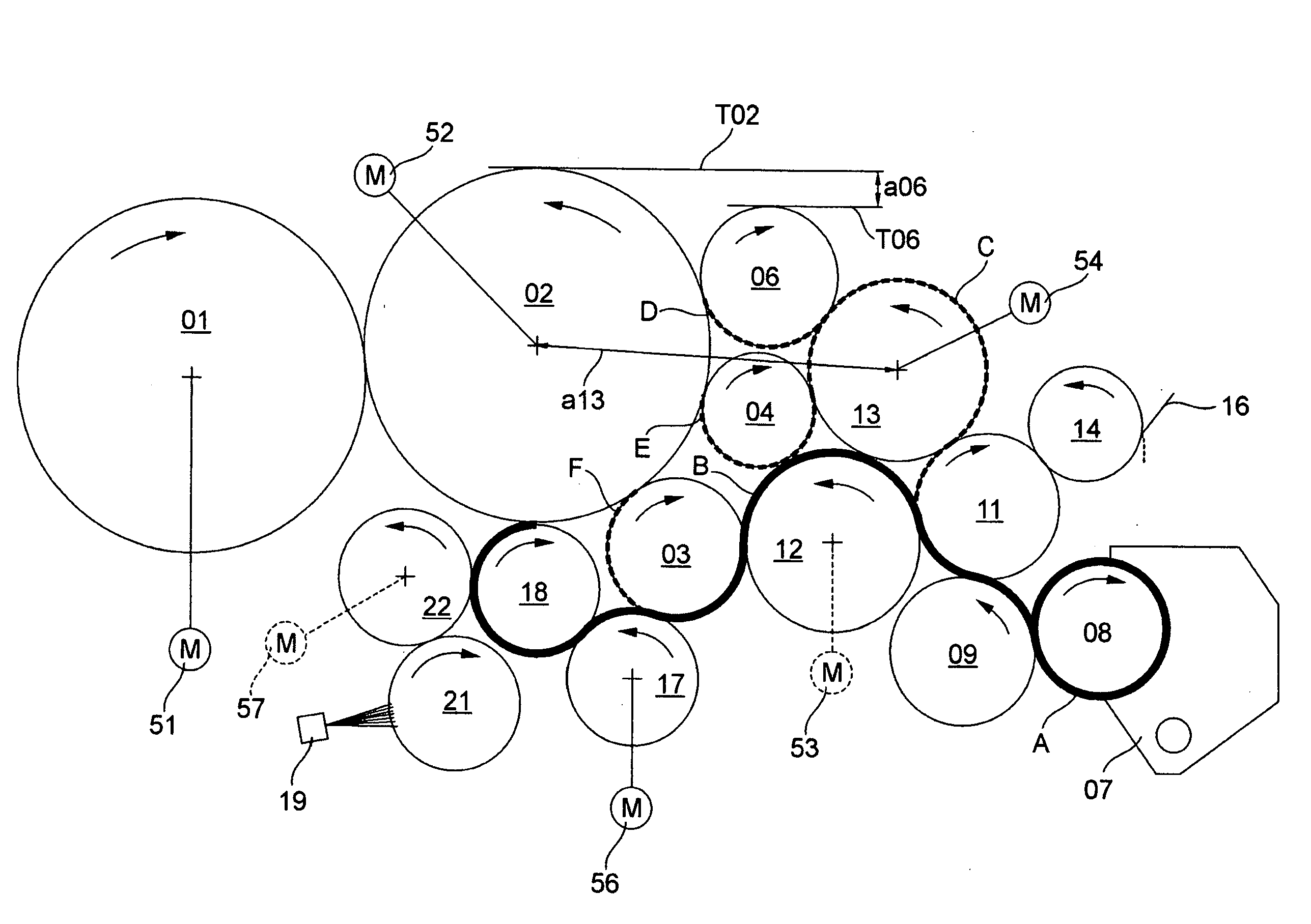
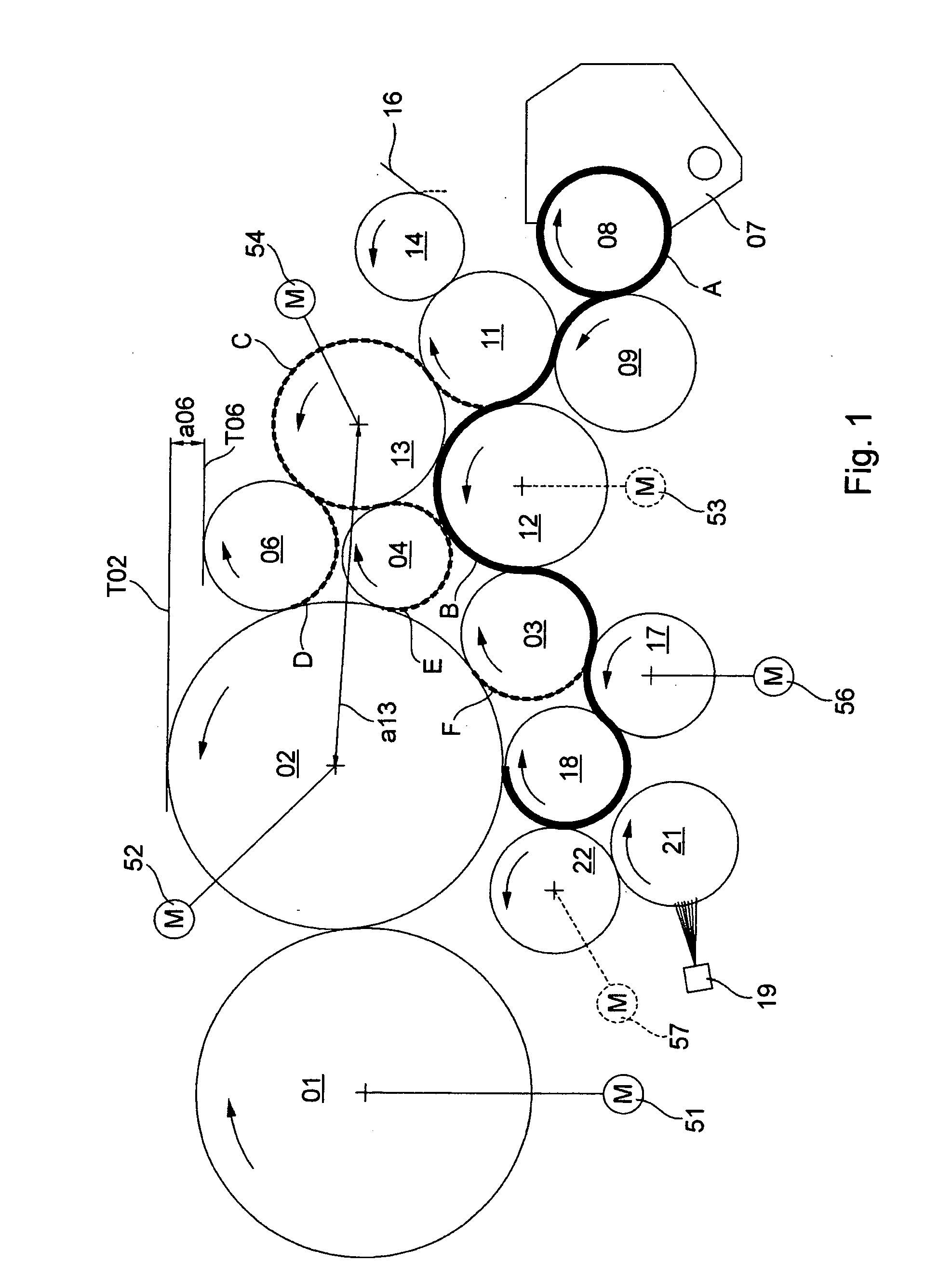
[0035]Referring initially to FIG. 1, a part of a printing couple of a rotary printing press is shown by way of example. In the represented example of FIG. 1, the rotary printing press operates using a wet offset printing process. Such a printing press is intended especially for use in newspaper printing. As printing couple cylinders 01; 02, the printing couple depicted in FIG. 1 has at least one transfer cylinder 01 and at least one forme cylinder 02 which cooperates with the associated transfer cylinder 01. Each time it rotates, the transfer cylinder 01 produces at least one printed image on a print substrate, preferably on a material web, especially on a paper web, which is not specifically shown here. When the printing couple is in the operating position that is shown in FIG. 1, at least one inking unit and one dampening unit are engaged against the forme cylinder 02.

[0036]The inking unit which is shown in FIG. 1 has a plurality of ink forme rollers, preferably at least three, 03...


PUM

PropertyMeasurementUnit
depthaaaaaaaaaa
vertical distanceaaaaaaaaaa
speedaaaaaaaaaa

Abstract

An inking unit of a rotary printing press includes a film roller. The film roller has a structured outer surface that has a Shore D hardness ranging between 80 and 90 and a stochastic surface. The stochastic surface is incorporated into the outer surface of the film roller by peening.

Description

CROSS-REFERENCE TO RELATED APPLICATIONS[0001]This application is the U.S. National phase, under 35 U.S.C. 371, of PCT / EP2007 / 053701, filed Apr. 17, 2007; published as WO 2007 / 134919 on Nov. 29, 2007 and claiming priority to DE 10 2006 024 029.4, filed May 23, 2006; to DE 10 2006 030 057.2, filed Jun. 29, 2006 and to DE 2006 042 590.1, filed Sep. 11, 2006, the disclosures of which are expressly incorporated herein by reference.FIELD OF THE INVENTION[0002]The present invention is directed to an inking unit of a rotary printing press comprising a film roller. The film roller has a structured circumferential surface that has a hardness of at least 60 Shore D. The surface has a stochastic structure which is imparted to the surface using shot peening.BACKGROUND OF THE INVENTION[0003]An inking unit of a rotary printing press comprising a film roller is known from JP 2005 271407A. The film roller has a circumferential surface with a coating of an 11-polyamide / 12-polyamide or of copper.[0004...

Claims


Application Information

Patent Timeline
Patent Type & Authority Applications(United States)
IPC IPC(8): B41F31/00
CPCB41F7/26B41F13/30B41F31/00B41F31/04B41F31/26B41N2207/10B41F31/301B41F31/36B41N7/06B41N2207/02B41N2207/14B41F31/30
Inventor SCHNEIDER, GEORGMASUCH, BERND KURT
Owner KOENIG & BAUER AG
Why Eureka
Try Eureka