
Method for determining a torque characteristic of an automated friction clutch

a technology of friction clutch and torque characteristic, which is applied in the direction of slip coupling, coupling, instruments, etc., can solve the problems of poor precision of fixed point determination, strong temperature-dependent and increasing drag torque, and delay in normal driving operation of motor vehicles, etc., to achieve the effect of more accurate determination

Inactive Publication Date: 2009-04-09
ZF FRIEDRICHSHAFEN AG
View PDF8 Cites 12 Cited by
  • Summary
  • Abstract
  • Description
  • Claims
  • Application Information

AI Technical Summary

Benefits of technology

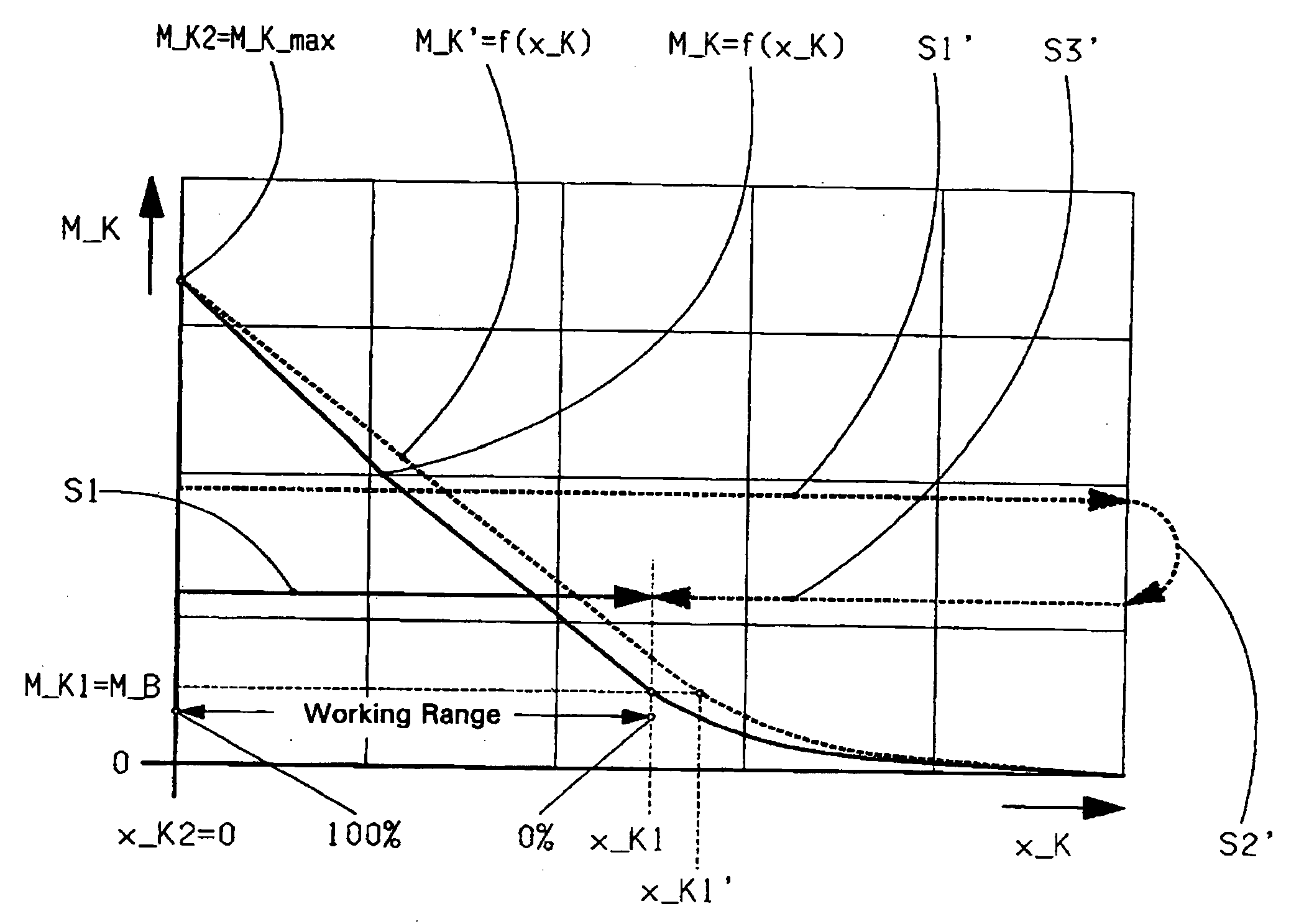
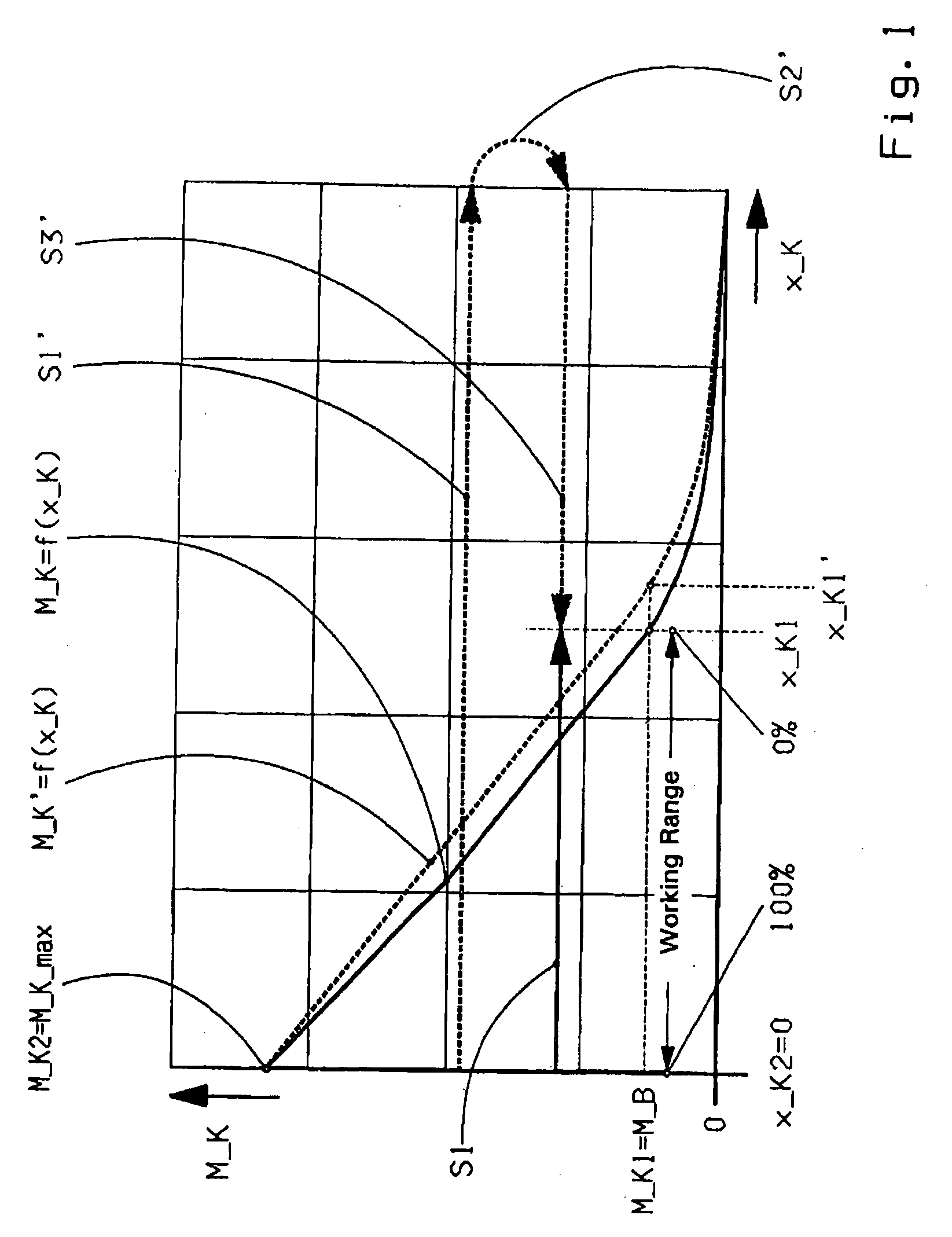
[0015]Moreover, the determination of the first marker point M_K1(x_K1) can be accelerated, at the latest before the slippage limit of the friction clutch is reached, if a transmission brake that acts upon the input shaft of the transmission or a synchronization device of a transmission gear is actuated. In this case, the braking torque M_B that acts upon the transmission input shaft is formed by the sum of the drag torque and the braking torque of the transmission brake or synchronization device. Consequently, the torque value M_K1 determined is larger in such a case, but can be determined more accurately because the operating temperature and the measurement errors have less effect.
[0017]The position range, between the two marker points M_K1(x_K1) and M_K2(x_K2) determined in this manner, is appropriately defined as the working range of the friction clutch for producing torque values M_K1(x_K1) with M_K1(x_K1)=0% and M_K2(x_K2)=100%. This then makes it possible to produce a desired, discrete torque value M_K1 and a desired time variation of the clutch torque M_K, for example for starting, maneuvering, shifting and stopping.

Problems solved by technology

With such friction clutches, the fundamental problem arises of determining a torque characteristic M_K=f(x_K) which represents the transferable torque M_K of the friction clutch as a function of the regulating path x_K of an associated clutch control element, such as a hydraulic or pneumatic control cylinder or a transfer element connected thereto, such as a disengagement lever or release bearing, by way of which the desired transferable torque of the friction clutch is controlled.
In addition, the drag torque is strongly temperature-dependent and increases as the operating temperature falls, in particular the oil temperature of the transmission.
The disadvantage of this known method for determining a torque characteristic are the large number of process steps needed, the relatively long duration of the process sequence, which can lead to delays during normal driving operation of the motor vehicle, and the relatively poor precision of the fixed point determinations.

Method used


Image

  • Method for determining a torque characteristic of an automated friction clutch
  • Method for determining a torque characteristic of an automated friction clutch
  • Method for determining a torque characteristic of an automated friction clutch

Examples


Embodiment Construction

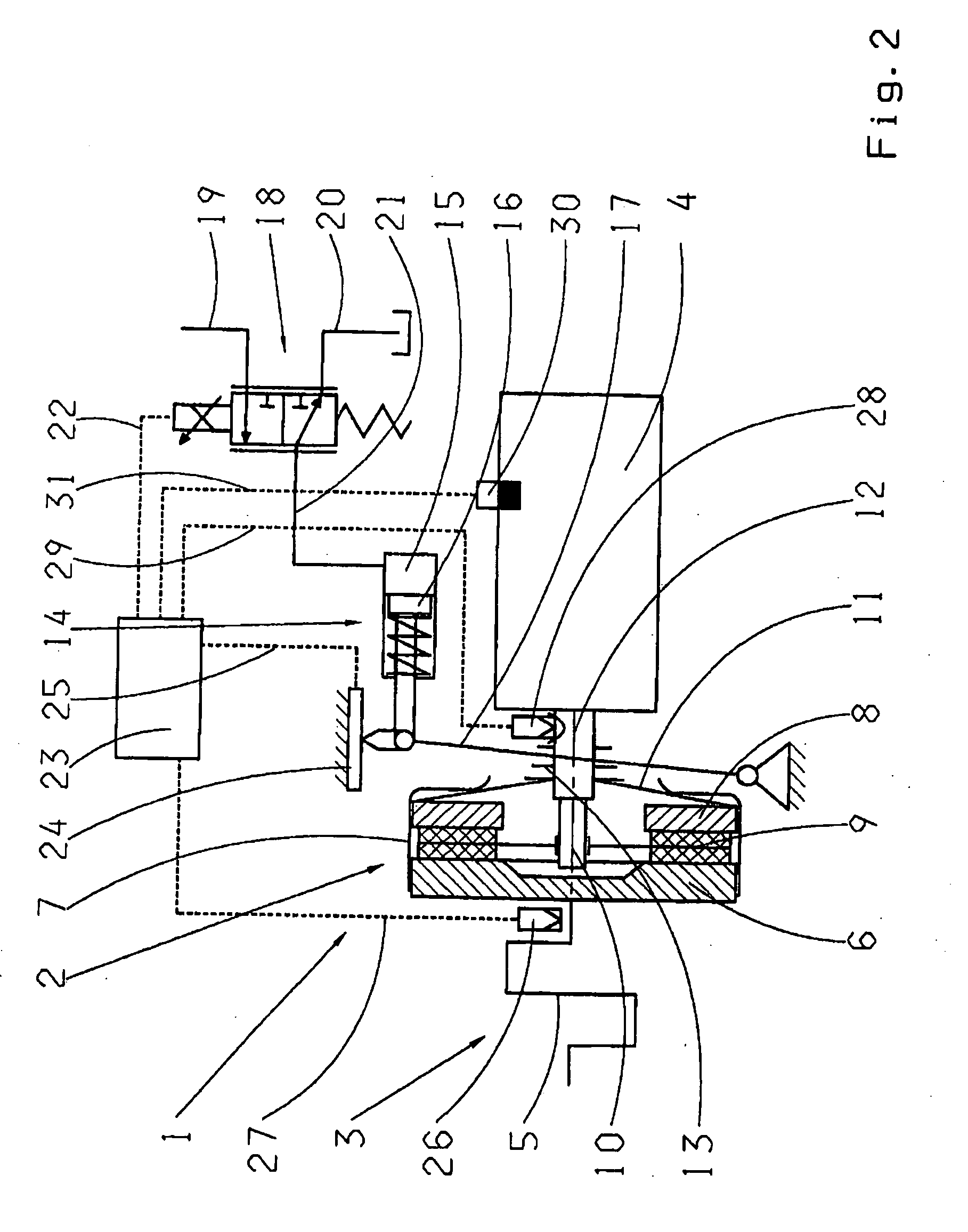
[0020]FIG. 2 shows an example of a clutch arrangement 1 for implementing a method according to the invention. In the Figure, a friction clutch 2, made as a single-disk, dry clutch, is shown arranged in the force flow between a drive engine 3 made as a piston-driven internal combustion engine and a drive transmission 4.

[0021]The part of the friction clutch 2 on its input side is formed by a flywheel 6 attached to a crankshaft 5 of the drive engine 3 and a pressure plate 8 connected thereto via a clutch cage 7. The part of the friction clutch 2 on its output side is formed by a carrier disk 9 arranged axially between the flywheel 6 and the pressure plate 8, which is mounted rotationally fixed to, but able to move axially on an input shaft 10 of the transmission 4. By virtue of a contact pressure spring 11 made as a membrane spring and arranged between the clutch cage 7 and the pressure plate 8, the friction clutch 2 is engaged in its rest position free from any control force, but can ...


PUM


Abstract

A method for determining a torque characteristic of a friction clutch located in a drive train of a motor vehicle in the force flow between a drive engine and a transmission and which is closed in its rest position. At least two marker points of a regulating-path-dependent torque characteristic are determined, one of which is determined at a slipping limit of the clutch. To enhance determination of the torque characteristic, a first marker point is determined with the clutch engaged, the transmission in neutral and the engine running, by slowly disengaging the clutch until a reduction in the speed of the transmission input shaft relative to the engine speed is detected. A corresponding pair of values of this marker point with the known braking torque of the input shaft and the set position are used for adapting an existing characteristic.

Description

[0001]This application is a national stage completion of PCT / EP20071054011 filed Apr. 25, 2007, which claims priority from German Application Serial No. 10 2006 019 824.7 filed Apr. 28, 2006.FIELD OF THE INVENTION[0002]The invention concerns a method for determining a torque characteristic of an automated friction clutch arranged in a drive train of a motor vehicle in the force flow between a drive engine and a drive transmission and which is engaged in the rest position, such that at least two marker points M_K1(x_K1), M_K2(x_K2) of a regulating-path-dependent torque characteristic M_K=f(x_K) are determined, of which at least one marker point is determined at a slippage limit of the friction clutch.BACKGROUND OF THE INVENTION[0003]The invention relates to all possible friction clutch structures that are engaged in the rest position. A generally known structural form with which the method, according to the invention, can preferably be applied, is a dry clutch that can be engaged pas...

Claims


Application Information

Patent Timeline
IPC IPC(8): F16D48/06
CPCF16D48/066F16D2500/10412F16D2500/1045F16D2500/3026Y10T477/70F16D2500/30816F16D2500/50254F16D2500/50263F16D2500/50272F16D2500/30406F16D2500/30401F16D2500/30412F16D2500/3067F16D2500/30803F16D2500/30808F16D2500/70472F16D2500/70605
Inventor PETZOLD, RAINERHERTER, PETERBITZER, FRANZ
Owner ZF FRIEDRICHSHAFEN AG
Learn More