
Process for making a micro-fluid ejection head structure

a technology of ejection head and nozzle plate, which is applied in the direction of metal-working equipment, printing, writing implements, etc., can solve the problems of requiring specialized equipment, affecting the precision of manufacturing parts that meet such demands, and requiring specialized equipment, so as to improve the nozzle plate and thick film layer, improve the nozzle structure, and improve the effect of nozzle plate and thickness

Active Publication Date: 2009-04-09
SLINGSHOT PRINTING LLC
View PDF1 Cites 12 Cited by
  • Summary
  • Abstract
  • Description
  • Claims
  • Application Information

AI Technical Summary

Benefits of technology

[0002]Micro-fluid ejection heads are useful for ejecting a variety of fluids including inks, cooling fluids, pharmaceuticals, lubricants and the like. A widely used micro-fluid ejection head is in an ink jet printer. Ink jet printers continue to be improved as the technology for making the micro-fluid ejection heads continues to advance. New techniques are constantly being developed to provide low cost, highly reliable printers which approach the speed and quality of laser printers. An added benefit of ink jet printers is that color images can be produced at a fraction of the cost of laser printers with as good or better quality than laser printers. All of the foregoing benefits exhibited by ink jet printers have also increased the competitiveness of suppliers to provide comparable printers in a more cost efficient manner than their competitors.
[0011]An advantage of the embodiments described herein is that they may provide an improved micro-fluid ejection head structures and, in particular, improved nozzle plates and thick film layers for micro-fluid ejection heads. Another advantage is that the methods may enable the formation of nozzle holes, fluid ejection chambers, and fluid flow channels that have precise sizes and shapes. Other advantages of the embodiments described herein may include improved protection of the fluid ejection actuators by the presence of the tantalum oxide layer on an exposed surface of the fluid ejection actuators.BRIEF DESCRIPTION OF THE DRAWINGS

Problems solved by technology

The process of forming, aligning, and attaching the nozzle plates to the substrates is a relatively time consuming process and requires specialized equipment.
As the ejection heads become more complex to meet the increased quality and speed demands of consumers, it becomes more difficult to precisely manufacture parts that meet such demand.

Method used


Image

  • Process for making a micro-fluid ejection head structure
  • Process for making a micro-fluid ejection head structure
  • Process for making a micro-fluid ejection head structure

Examples


Embodiment Construction

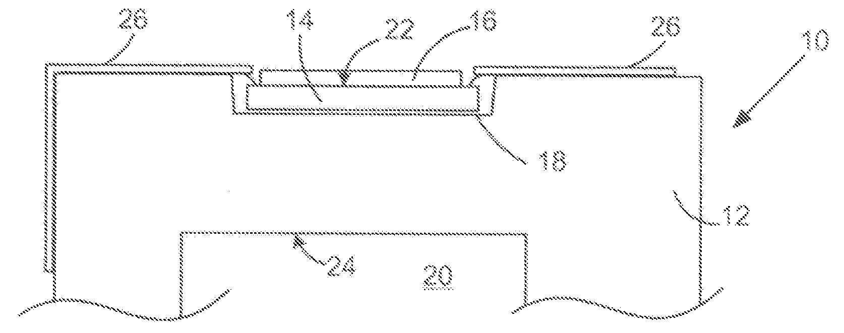
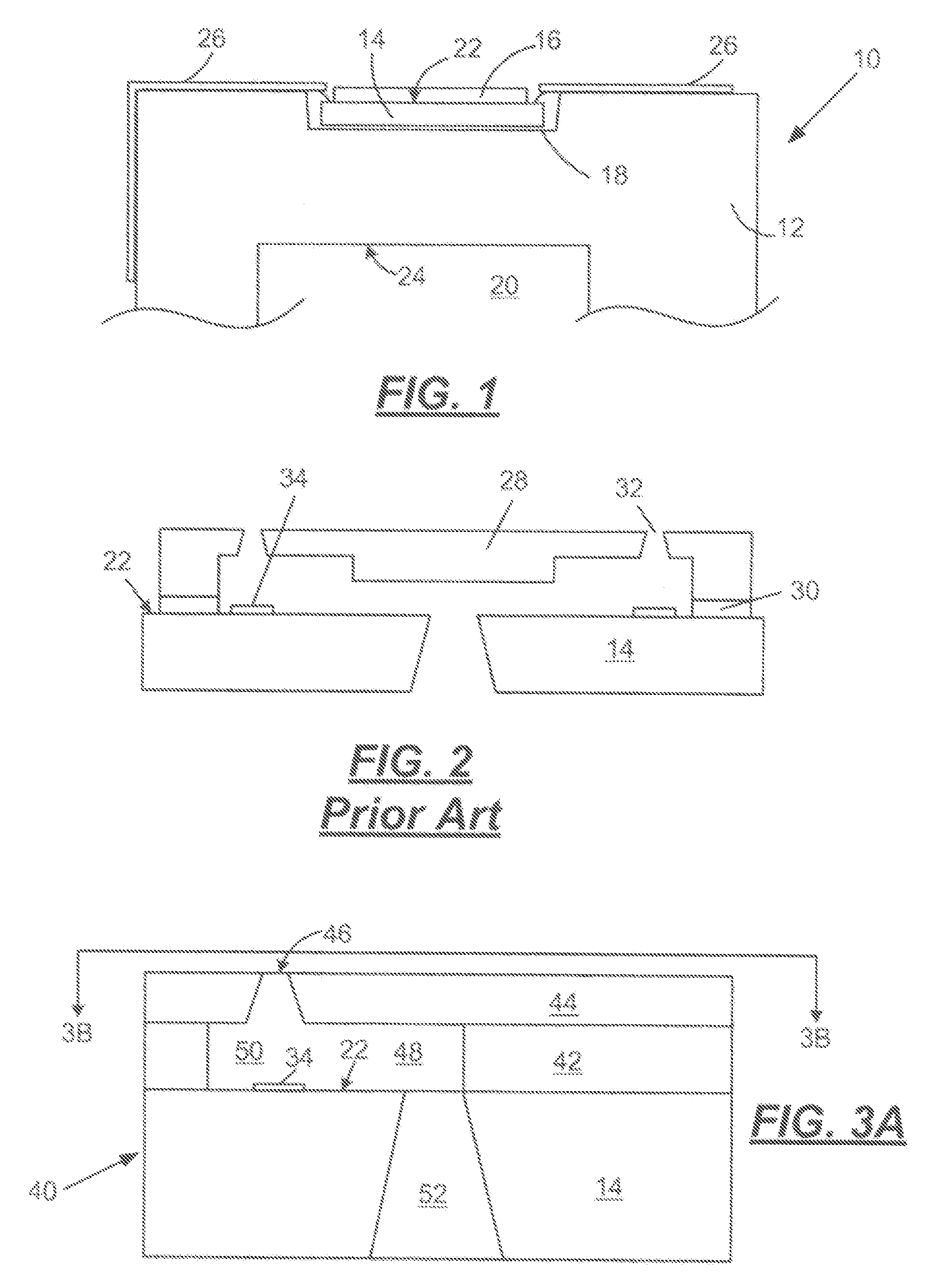
[0019]With reference to FIG. 1, there is shown a simplified representation of a portion of an exemplary micro-fluid ejection head 10, for example an ink jet printhead, viewed from one side and attached to a fluid cartridge body 12. The ejection head 10 includes a substrate 14 and a nozzle plate 16 attached to the substrate. The substrate / nozzle plate assembly 14 / 16 is attached in a chip pocket 18 in the cartridge body 12 to form the ejection head 10. Fluid to be ejected, such as an ink, is supplied to the substrate / nozzle plate assembly 14 / 16 from a fluid reservoir 20 in the cartridge body 12 generally opposite the chip pocket 18.

[0020]The cartridge body 12 may preferably be made of a metal or a polymeric material selected from the group consisting of amorphous thermoplastic polyetherimide available from G.E. Plastics of Huntersville, N.C. under the trade name ULTEM 1010, glass filled thermoplastic polyethylene terephthalate resin available from E. I. du Pont de Nemours and Company ...


PUM

PropertyMeasurementUnit
thicknessaaaaaaaaaa
refractive indexaaaaaaaaaa
sizeaaaaaaaaaa

Abstract

A method of making a micro-fluid ejection head structure and micro-fluid ejection heads made by the method. The method includes applying a tantalum oxide layer to a surface of a fluid ejection actuator disposed on a device surface of a substrate so that the tantalum oxide layer is the topmost layer of a plurality of layers including a resistive layer, and a protective layer selected from a passivation layer, a cavitation layer, and a combination of a passivation layer and a cavitation layer. The tantalum oxide layer has a thickness (t) that satisfies an equation t=(¼*W / n), wherein W is a wavelength of radiation from a radiation source, and n is a refractive index of the tantalum oxide layer. A photoimageable layer is also applied to the substrate. The photoimageable layer is imaged with the radiation source and then developed.

Description

TECHNICAL FIELD[0001]The disclosure relates to micro-fluid ejection devices, and in particular to improved methods for making micro-fluid ejection head structures that have precisely formed flow features.BACKGROUND AND SUMMARY[0002]Micro-fluid ejection heads are useful for ejecting a variety of fluids including inks, cooling fluids, pharmaceuticals, lubricants and the like. A widely used micro-fluid ejection head is in an ink jet printer. Ink jet printers continue to be improved as the technology for making the micro-fluid ejection heads continues to advance. New techniques are constantly being developed to provide low cost, highly reliable printers which approach the speed and quality of laser printers. An added benefit of ink jet printers is that color images can be produced at a fraction of the cost of laser printers with as good or better quality than laser printers. All of the foregoing benefits exhibited by ink jet printers have also increased the competitiveness of suppliers ...

Claims


Application Information

Patent Timeline
Patent Type & Authority Applications(United States)
IPC IPC(8): B41J2/05B23P17/00
CPCB41J2/1603B41J2/1628B41J2/1631Y10T29/49401B41J2/1642B41J2/1645B41J2/1634
Inventor BELL, BYRON VENCENTCRAFT, CHRISTOPHER ALLENFANNIN, BRYAN THOMASJOYNER, II, BURTON LEEWEAVER, SEAN TERRENCE
Owner SLINGSHOT PRINTING LLC
Learn More