
Cooled ablation catheter devices and methods of use

a catheter device and cooling technology, applied in the field of cooling ablation catheter devices and methods of use, can solve the problems of difficult creation of suitable lesions using these catheters, long patient recovery period, and high invasiveness of open heart surgery, and achieve the effect of reducing the formation of coagulum and minimizing the effect of biological debris on the delivery of energy to tissu

Active Publication Date: 2009-04-09
BOSTON SCI SCIMED INC
View PDF39 Cites 145 Cited by
  • Summary
  • Abstract
  • Description
  • Claims
  • Application Information

AI Technical Summary

Benefits of technology

The patent describes a device for medical treatment that can deliver ablative energy to target tissue while reducing the formation of coagulum and minimizing the effects of biological debris on the delivery of energy to tissue. The device includes an ablation catheter with an ablative electrode tip. The tip has a cooling system that circulates cooling fluid through the tip and is designed to cool the surrounding tissue. The cooling system can include a proximal cooling chamber and a distal cooling chamber that work together to cool the tip. The cooling system can also include multiple irrigation apertures for delivering cooling fluid to the environment surrounding the tip. The device can be sized and shaped for vascular access and can include a second fluid lumen for the removal of cooling fluid from the tip. The open and closed loop flow paths can be separate from each other. Overall, the device can improve the effectiveness of medical treatment and minimize damage to the surrounding tissue.

Problems solved by technology

However, because open heart surgery is highly invasive and requires a lengthy patient recovery period, alternative methods for making lesions have been recently explored.
However, because of the tendency for the tip electrode to overheat and to lift off the tissue surface during ablation, creating suitable lesions using these catheters have been difficult.
Although these catheters mitigate some of the overheating problems, hotspots on the tip or in adjacent tissue may still develop.

Method used


Image

  • Cooled ablation catheter devices and methods of use
  • Cooled ablation catheter devices and methods of use
  • Cooled ablation catheter devices and methods of use

Examples


Embodiment Construction

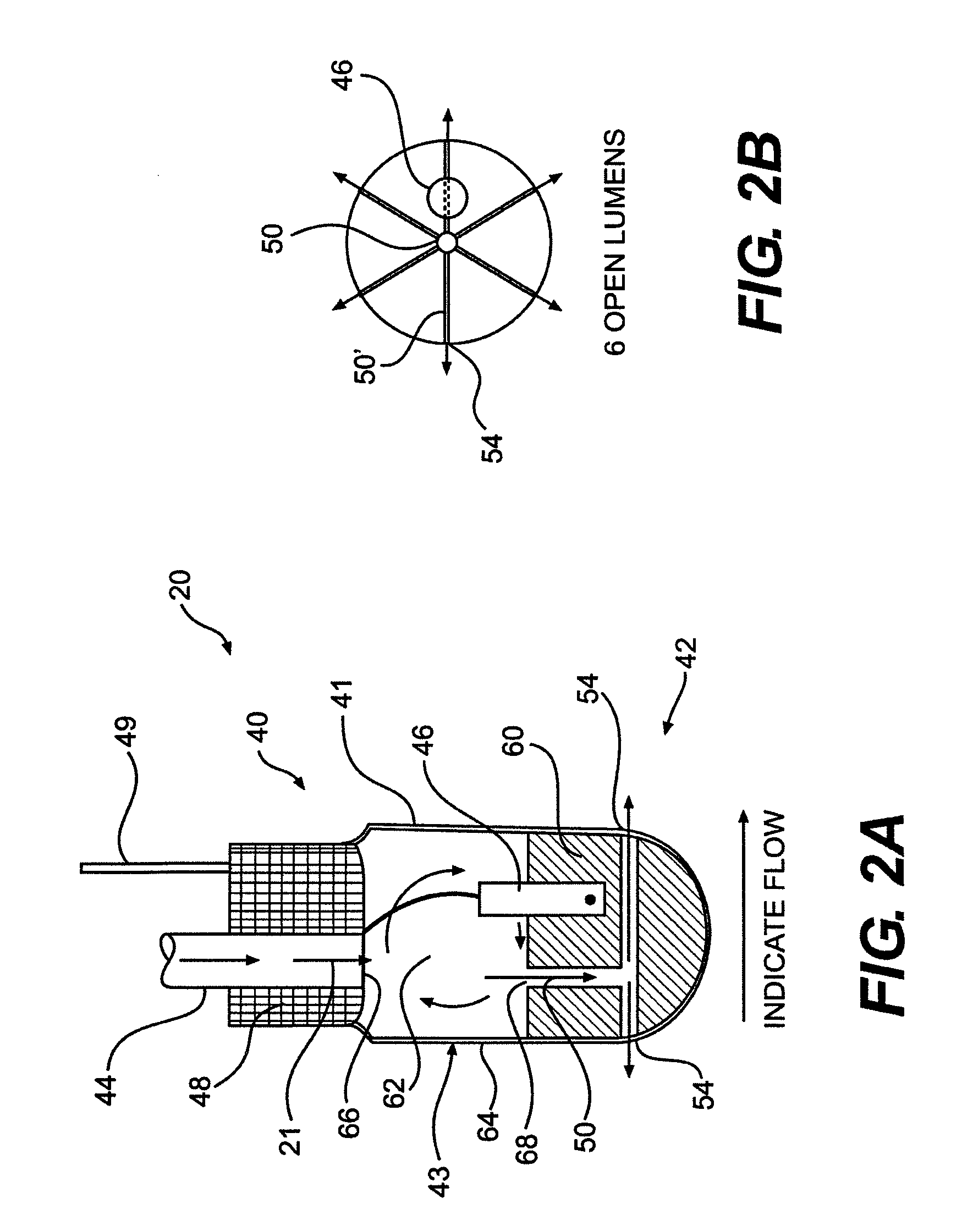
[0030]Disclosed herein are cooled ablation catheters and methods of use. In general, the catheters include a flow path that provides cooling to a distal tip. The catheter can include an electrode tip having irrigation apertures for delivery of a cooling fluid to the environment surrounding the distal tip and / or to the surface of the distal tip. In addition, the electrode tip can comprise a proximal cooling chamber through which cooling fluid circulates prior to egress through the irrigation apertures. The proximal cooling chamber can reduce hotspots sometimes associated with conventional ablation catheters.

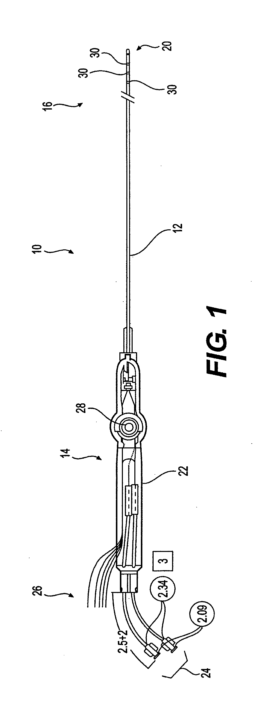
[0031]FIG. 1 provides a cut-away view of one exemplary embodiment of an ablation catheter device 10 for use with the distal tip structure described herein. Device 10 can include an elongate body 12 extending between a proximal section 14 and a distal section 16. The distal section includes an electrode tip 20 positioned to deliver ablative energy to tissue and is discussed in deta...


PUM


Abstract

Discloses herein are ablative catheters and methods of use. The catheters can include a cooling chamber for circulating cooling fluid within the catheter tip to reduce hot spots within the catheter tip and / or to reduce the formation of coagulum. A proximal cooling chamber can be positioned proximally to a thermal mass for cooling a proximal portion of the catheter. In addition, or alternatively, a distal cooling chamber can be positioned for cooling a distal portion of the catheter tip. The cooling fluid can flow the ablative catheter in an open, closed, or open and closed loop.

Description

[0001]This application claims priority to Provisional Application Ser. No. 60 / 978,511 entitled “Cooled Ablation Catheter Devices and Methods of Use” filed Oct. 9, 2007, which is incorporated herein by reference.BACKGROUND[0002]Atrial fibrillation is a condition in the heart in which the generation of abnormal electrical signals causes irregular beatings of the heart. A proven protocol for successfully treating this condition is open heart surgery (sometimes referred to as the “maze” procedure) where several long (i.e. approximately 2-10 cm) lesions are created in the endocardium within the upper chambers of the heart (“atria”). These lesions block the flow of excess electrical impulses within the atria and allow the impulse from the sinus node to properly regulate heart contraction.[0003]However, because open heart surgery is highly invasive and requires a lengthy patient recovery period, alternative methods for making lesions have been recently explored. One such alternative is the...

Claims


Application Information

Patent Timeline
Patent Type & Authority Applications(United States)
IPC IPC(8): A61B18/14
CPCA61B18/1492A61N1/06A61B2218/002A61B2018/00821
Inventor KOBLISH, JOSEFOLEY, LESLIE
Owner BOSTON SCI SCIMED INC
Learn More