Implantable Joint Prosthesis

a joint replacement and implantable technology, applied in the field of joint replacement prosthesis, can solve the problems of inability to repair, further damage to the joint, and significant pain to the individual, and achieve the effect of reducing the tendency for mode coupling

Inactive Publication Date: 2009-04-09
SILESCO
View PDF10 Cites 99 Cited by
  • Summary
  • Abstract
  • Description
  • Claims
  • Application Information

AI Technical Summary

Benefits of technology

[0055]In another embodiment, the geometric structure of the first and / or second components are modified such that the resonant frequency of the first component is mismatched with the resonant frequency of the second component to reduce the tendency for mode coupling between the two components.

Problems solved by technology

Through disease, injury or old age, the cartilage may become damaged causing the tissue around the joint to become inflamed and hence cause pain to the individual, which over time, can cause the cartilage to erode, thereby resulting in the rough edges of the bone contacting and rubbing against each other causing further damage to the joint and significant pain to the individual.
However, if the entire joint becomes damaged or deteriorates significantly through such conditions as osteoarthritis, rheumatoid arthritis, or avascular necrosis, reparative treatment may not be possible and a more radical treatment may be necessary.
Such implants tend to wear over time as the plastic material wears out.
Whilst hip replacement surgery has been proven relatively successful in restoring movement to individuals and relieving pain previously experienced in the joint, in some instances an undesirable outcome has been the presence of an audible squeak associated with the implant in some individuals.
Such a squeak may be experienced by the individual when bending or during walking and can be a source of embarrassment and distress to the individual.
While such a locking mechanism may perform adequately under generally axial loads they do not perform well under other loadings and in particular edge loading.
Such uncoupling may lead to undesirable squeaking of the prosthesis.

Method used


Image

  • Implantable Joint Prosthesis
  • Implantable Joint Prosthesis
  • Implantable Joint Prosthesis

Examples


Embodiment Construction

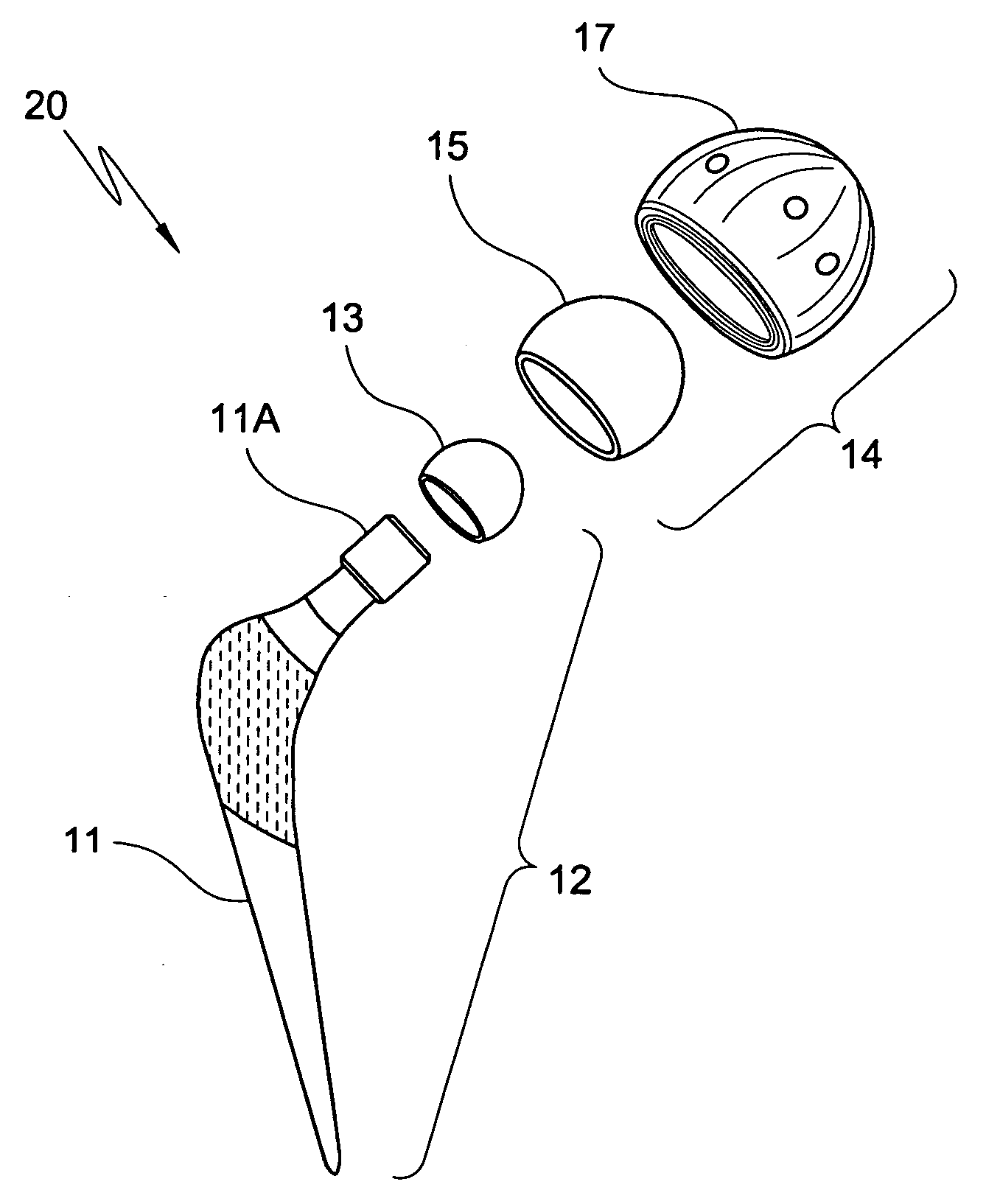
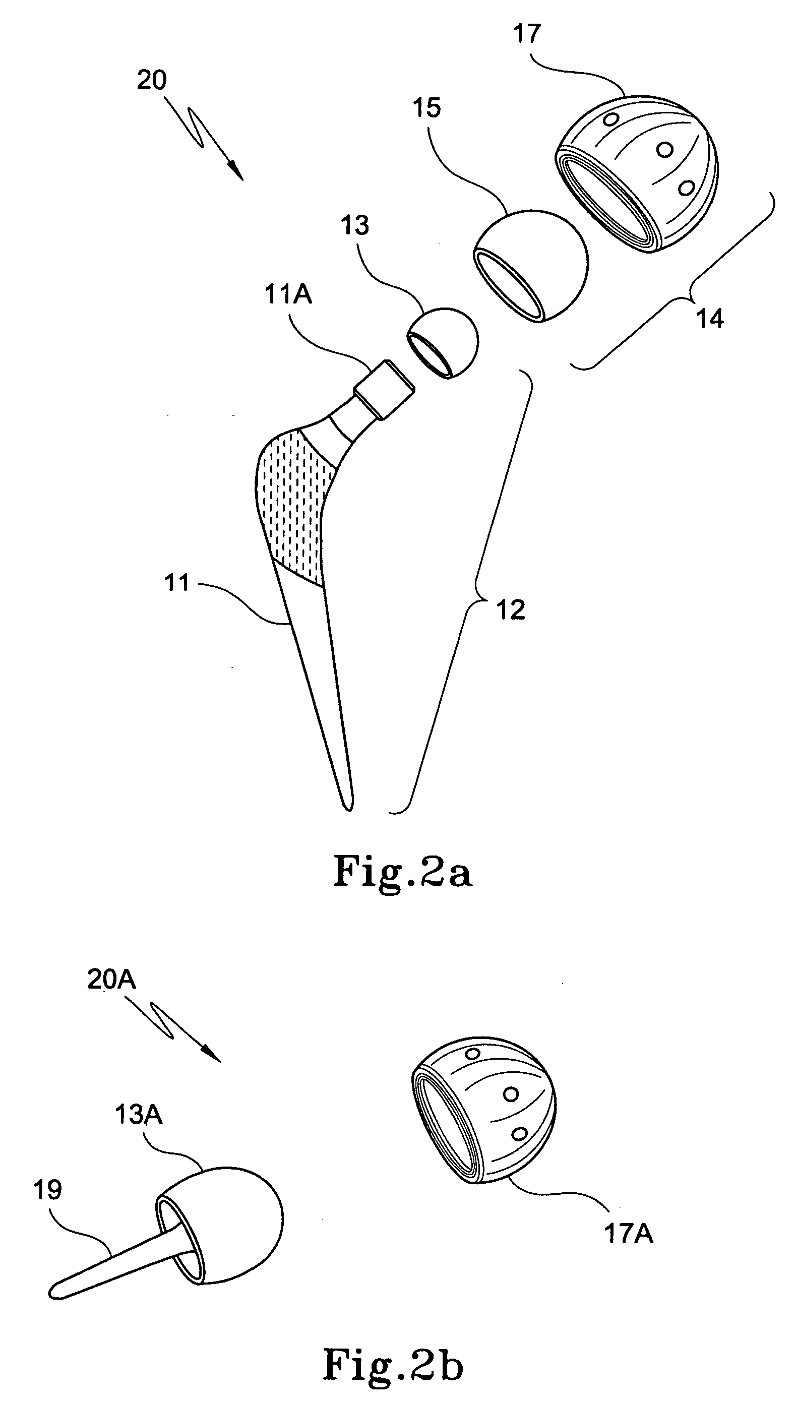
[0101]The present invention will be described in relation to a hip joint prosthesis, however it will be appreciated by a person skilled in the art that the present invention could be equally be applied to a prosthesis suitable for use with any joint, whether the prosthesis be a partial or full replacement of the natural joint.

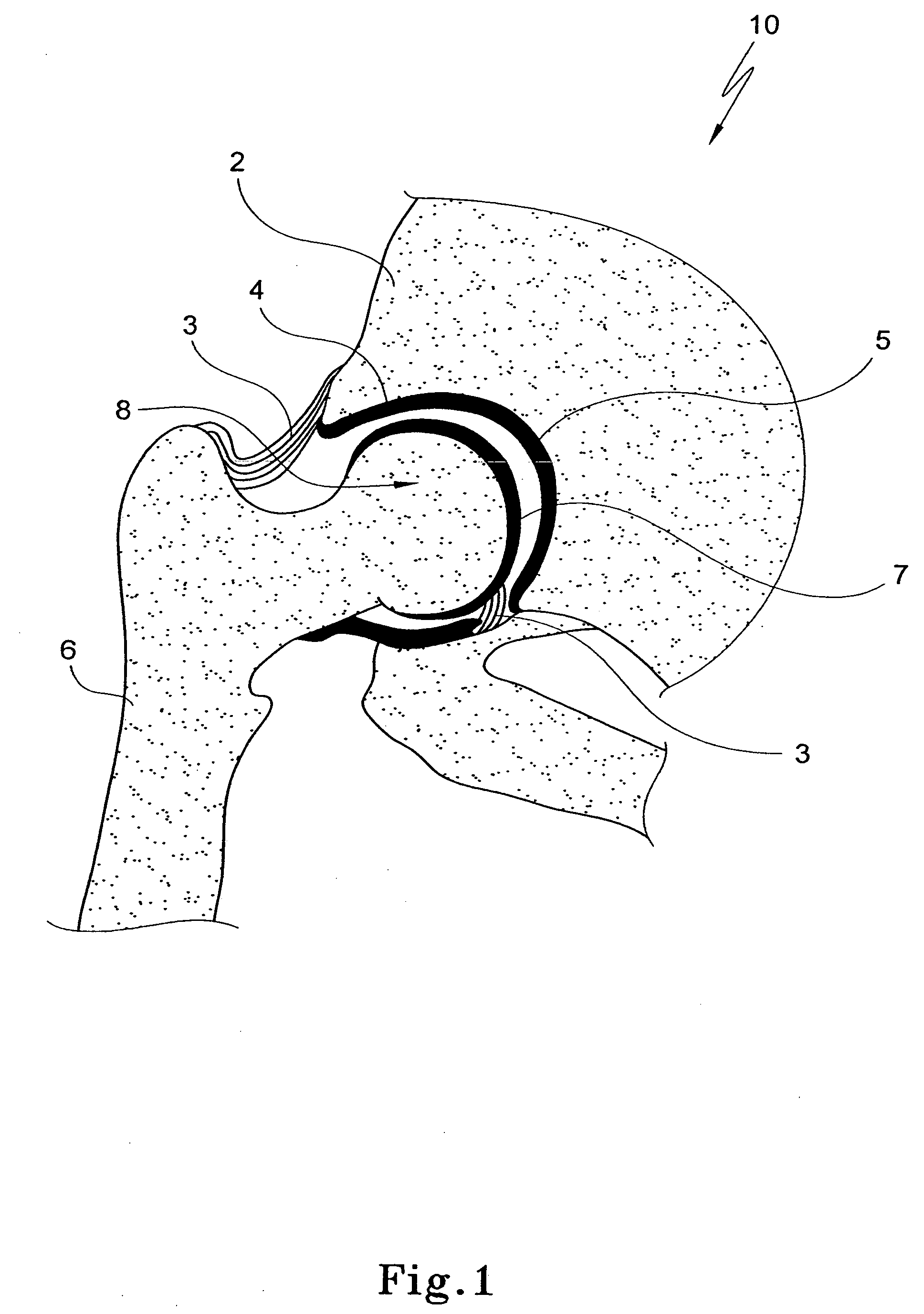
[0102]With regard to FIG. 1, a part of a normal hip joint 10 is shown. The hip joint 10 generally functions to connect the legs to the torso of an individual, and hence comprises the pelvis 2 having the acetabulum (or socket) 4 into which the head 8 of the femur 6 is received. As can be seen, the hip joint 10 is a ball and socket joint that provides multiple degrees of movement between the individual's legs and the pelvis to facilitate a variety of activities such as walking and running.

[0103]Cartilage 5, 7 lines the acetabulum 4 and head 8 of the femur respectively to provide a cushioning function to the joint 10 and to prevent the bones from rubbing together....


PUM


Abstract

An implantable joint prosthesis configured such that it does not squeak during movements of a subject. The joint prosthesis includes a means to modify the dynamic response of parts of the prosthesis such the response is not audible to the human ear.

Description

CROSS-REFERENCE TO RELATED APPLICATIONS[0001]The present application claims priority from Australian Provisional Patent Application No 2006900086, Australian Provisional Patent Application No 2006900406, Australian Provisional Patent Application No 2006901324, Australian Provisional Patent Application No 2006904349 filed on 9 Jan. 2006, 27 Jan. 2006, 15 Mar. 2006, 19 Aug. 2006, the contents of which are incorporated herein by reference.FIELD OF THE INVENTION[0002]The present invention relates to a joint replacement prosthesis for implantation into the body of an individual, in particular to a joint replacement prosthesis which can function to replace at least a part of the joint of an individual and which can operate in a substantially quiet mode.BACKGROUND ART[0003]Joints, such as the hip, knee, ankle, elbow and shoulder, are formed by the ends of two or more bones connected by cartilage tissue, which in healthy joints, acts as a protective cushion for the joint, allowing smooth, l...

Claims


Application Information

Patent Timeline
Patent Type & Authority Applications(United States)
IPC IPC(8): A61F2/32A61F2/30
CPCA61B17/86A61F2/30721A61F2/30724A61F2/32A61F2/34A61F2/36A61F2/3603A61F2/3662A61F2/367A61F2/3672A61F2/3676A61F2/46A61F2/468A61F2002/30004A61F2002/30014A61F2002/30024A61F2002/30125A61F2002/30156A61F2002/30179A61F2002/302A61F2002/30322A61F2002/30324A61F2002/30332A61F2002/30377A61F2002/3038A61F2002/30387A61F2002/30403A61F2002/30405A61F2002/30433A61F2002/30474A61F2002/30476A61F2002/30514A61F2002/30563A61F2002/30581A61F2002/30695A61F2002/30733A61F2002/30779A61F2002/30787A61F2002/30789A61F2002/30795A61F2002/30822A61F2002/30827A61F2002/3083A61F2002/30878A61F2002/30919A61F2002/30943A61F2002/30971A61F2002/325A61F2002/3291A61F2002/3401A61F2002/3406A61F2002/3419A61F2002/3422A61F2002/3432A61F2002/3438A61F2002/3448A61F2002/3611A61F2002/3625A61F2002/365A61F2002/3682A61F2002/3694A61F2002/4631A61F2002/4671A61F2002/481A61F2220/0025A61F2220/0033A61F2220/0041A61F2230/0008A61F2230/0023A61F2230/0058A61F2230/0065A61F2250/0014A61F2250/0018A61F2250/0021A61F2250/0026A61F2250/0036A61F2310/00011A61F2310/00017A61F2310/00023A61F2310/00029A61F2310/00179A61F2002/30331A61F2002/30367A61F2002/30495A61F2002/30593A61F2002/3241A61F2002/3417A61F2002/342A61F2002/368A61F2/481
Inventor WALTER, WILLIAM LINDSAYGILLIES, RONALD MARKDONOHOO, SHANE
Owner SILESCO
Why Eureka
Try Eureka