Gas liquifier

a cryocooler and gas liquefaction technology, which is applied in the field of gas liquefaction with a pulse tube cryocooler, can solve the problems of unreliable and costly, undesirably high boil-off rate of liquid helium, and inability to meet the needs of liquid helium supply, so as to reduce heat radiation

Active Publication Date: 2009-04-16
CRYOMECH
View PDF24 Cites 35 Cited by
  • Summary
  • Abstract
  • Description
  • Claims
  • Application Information

AI Technical Summary

Benefits of technology

[0013]A cryocooler for liquefying gas in which the neck of the dewar or cryostat or cryostat includes a cold end of a cryocooler with the first stage cooling station, the first stage regenerator, the second stage cooling station, the second stage regenerator, and a condenser thermally coupled to the second cooling s

Problems solved by technology

The systems are complicated, unreliable and costly.
Currently many helium dewars and helium cryostats for superconducting devices and low temperature physics in the field are not cryo-refrigerated and, thus, have an undesirably high liquid helium boil-off rate.
The world

Method used


Image

  • Gas liquifier
  • Gas liquifier
  • Gas liquifier

Examples


first embodiment

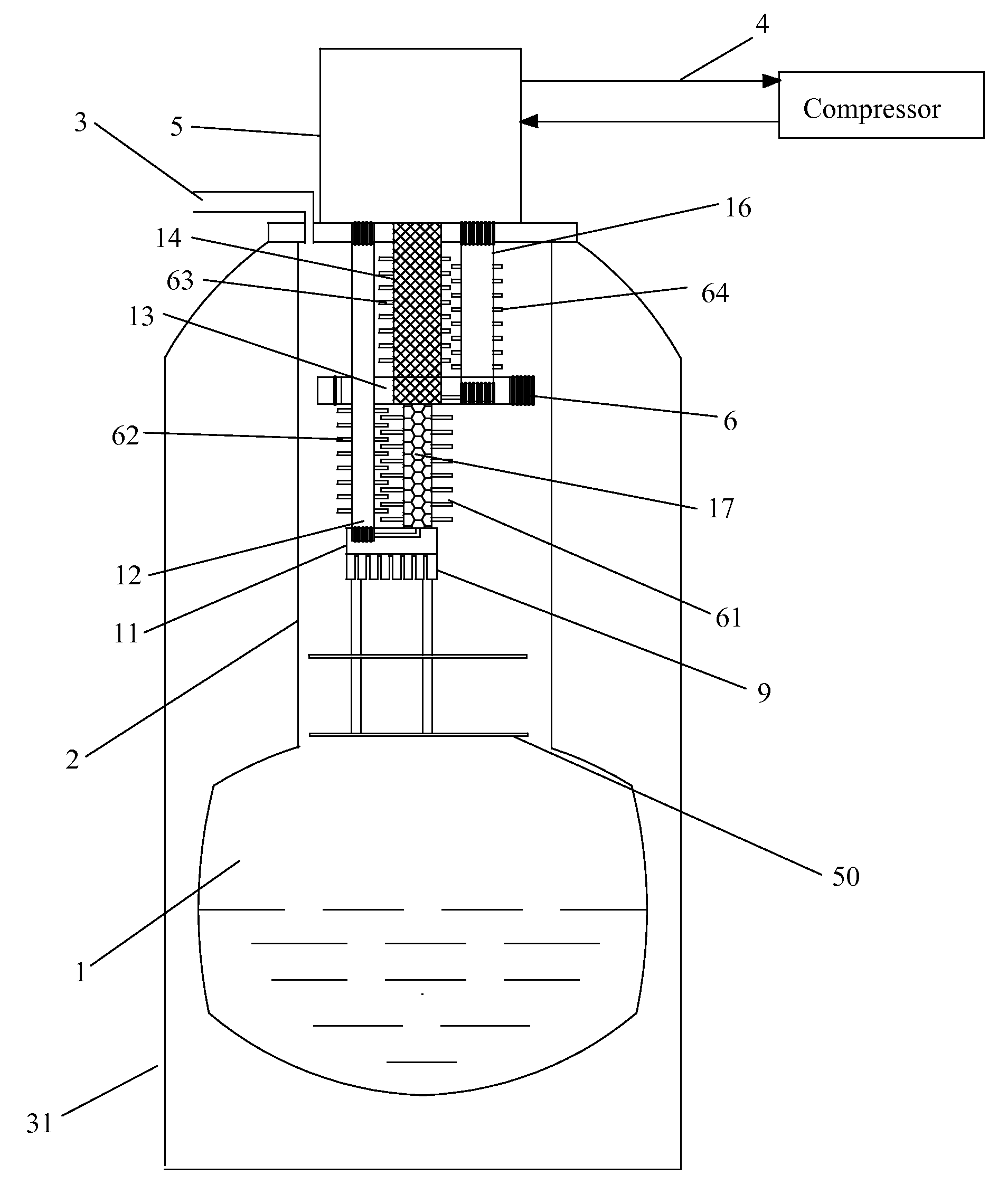
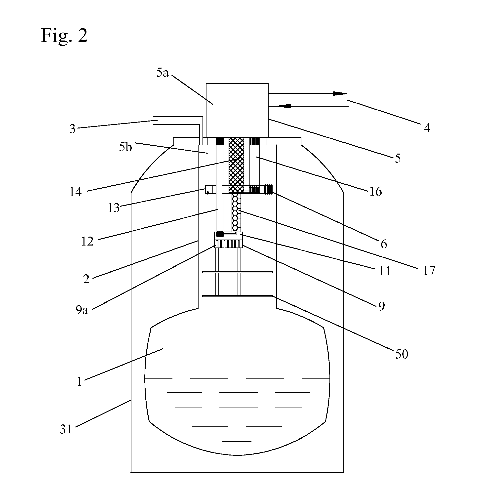
[0025]FIG. 2 shows helium liquefaction inside a dewar using a two stage pulse tube cryocooler of the present invention. The dewar or cryostat includes a neck 2, storage portion 1 and vacuum chamber 31. In present invention, the neck 2 of the dewar or cryostat extends up from the top end of the storage portion 1 containing cryogen, preferably helium to the room temperature end of the dewar or cryostat, upon which the cold head 5 sits. The neck 2 and the storage portion 1 are surrounded by a vacuum chamber 31. The cold head 5 has a hot end 5a outside of the neck 2 of the dewar or cryostat and a cold end 5b within the neck 2 of the dewar or cryostat.

[0026]The cold head 5 includes a first stage cooling station 13 and a second stage cooling station 11. The first stage cooling station 13 has a first stage temperature which is higher than the second stage temperature of the second stage cooling station 11. The first stage cooling station 13 includes pre-cooling heat exchanger 6. The second...

fourth embodiment

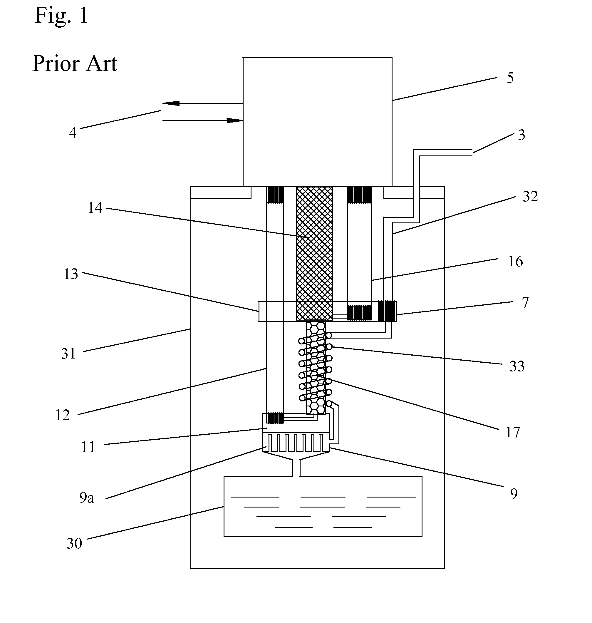
[0031]FIG. 5 shows the present invention. In this embodiment, pre-cooling spiral tubing 60 is thermally mounted to the second stage regenerator 17. The pre-cooling spiral tubing 60 provides additional surface for pre-cooling of the gas. The spiral tube 60 is open at each end. This is different from the pre-cooling spiral tubes in prior art FIG. 1, in which the gas is restrict to flow only in the tubing. In the present invention, gas can be precooled by flowing inside the tubing 60 and also by the outside surface of the spiral tubing 60 driven by natural convection.

fifth embodiment

[0032]FIG. 6 shows the present invention. In this embodiment, pre-cooling fins 61 are thermally mounted to the second stage regenerator 17. In the present invention, the gas is not restricted to a specific pathway of tubing, instead the gas flows over the tubes of regenerators and pulse tubes as well as the cooling stations within the neck 2 of the dewar or cryostat. The pre-cooling fins 61 provide additional surfacing for cooling of the gas. Since the pre-cooling fins 61 are not part of a specific gas path as in the prior art, the pre-cooling fins 61 cool the gas by natural convection. The fins 61 may be perforated plates, solid plates, brush fins, or other similar designs.


PUM


Abstract

A cryocooler for liquefying gas in which the neck of the dewar or cryostat includes a cold end of a cryocooler with the first stage cooling station, the first stage regenerator, the second stage cooling station, the second stage regenerator, and a condenser thermally coupled to the second cooling station. Radiation baffles are also present within the neck portion of the dewar between the storage portion for the dewar and the condenser, such that when the cryocooler is turned off, the radiation baffles reduce heat radiation on the cryogen in the storage section of the dewar.

Description

BACKGROUND OF THE INVENTION[0001]1. Field of the Invention[0002]The invention pertains to the field of gas liquefaction with a pulse tube cryocooler. More particularly, the invention pertains to liquefaction of gas by locating the cold head of a cryocooler within the neck of a dewar or cryostat.[0003]2. Description of Related Art[0004]While many laboratories and industries have applications which require liquid helium, at the present time the most widely used liquid helium producing system, such as the Collins type liquefier, is larger than most sites need to operate their experiments. Some small-scale helium liquefiers have been developed using a combined Gifford-McMahon and Joule-Thomson cycle refrigerator. The systems are complicated, unreliable and costly.[0005]Currently many helium dewars and helium cryostats for superconducting devices and low temperature physics in the field are not cryo-refrigerated and, thus, have an undesirably high liquid helium boil-off rate. The world's...

Claims


Application Information

Patent Timeline
IPC IPC(8): F25B9/14
CPCF25B9/10F25B2500/27F25B2400/17F25B9/14F25J1/0007F25J1/0225F25J1/0276F25J2270/91F25J2270/912
Inventor WANG, CHAO
Owner CRYOMECH
Why Eureka
Try Eureka