Drainpipe heat exchanger

a heat exchanger and drainpipe technology, applied in the direction of recuperative heat exchangers, stationary tubular conduit assemblies, heating/cooling energy-saving, etc., can solve the problems of heat exchangers, simple but expensive dhr heat exchangers, poor use of heat transfer surface area, etc., to achieve easy sliding and maximize thermal conduction

Inactive Publication Date: 2009-04-16
MACKELVIE WINSTON
View PDF11 Cites 12 Cited by
  • Summary
  • Abstract
  • Description
  • Claims
  • Application Information

AI Technical Summary

Benefits of technology

[0010]In one embodiment of the instant heat exchanger invention, sheet copper is formed into a hollow, tubular, sealed chamber or jacket having spaced inner and outer walls forming a cavity and where the inner wall matches the shape or form of the drainpipe to which the exchanger is to be attached. A longitudinal gap, slit or opening is provided where the inner and outer walls converge giving the chamber or jacket a “C” shape. This gap allows contraction of the inner wall tightly onto a circular drain tube when the exterior wall is clamped using band clamps acting on a stiff outer sleeve (for clamp force distribution). Thus an intimate contact between the thermal transfer surfaces, namely, the chamber or jacket inner wall and the drainpipe outer wall is made possible and yet the jacket can be easily slid onto the drainpipe from one end. In addition, normal mains cold water supply pressurizes the inside of the jacket. This pressure adds to the thermal contact force with the drainpipe thereby to maximize thermal conduction and so, the all important rate of heat transfer.

Problems solved by technology

This can be partly attributed to the poor use of the expensive heat transfer surface area.
Copper tubing for cold water coiled around a vertical copper drainpipe makes a simple but expensive DHR heat exchanger.
One of the weaknesses of such heat exchangers is the narrow spiral contact patch between the coil's inner surface and the tube's outer wall.
Because heat transfer is a direct function of surface area, the less than full contact area reduces performance from high cost materials.
Further, the long length of the coil tube (up to 100 feet long) and the fact that it flattens somewhat as it is wound, creates internal resistance to flow and an unwanted drop in water pressure for the heater.

Method used


Image

  • Drainpipe heat exchanger
  • Drainpipe heat exchanger
  • Drainpipe heat exchanger

Examples


Embodiment Construction

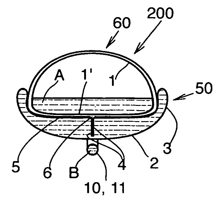
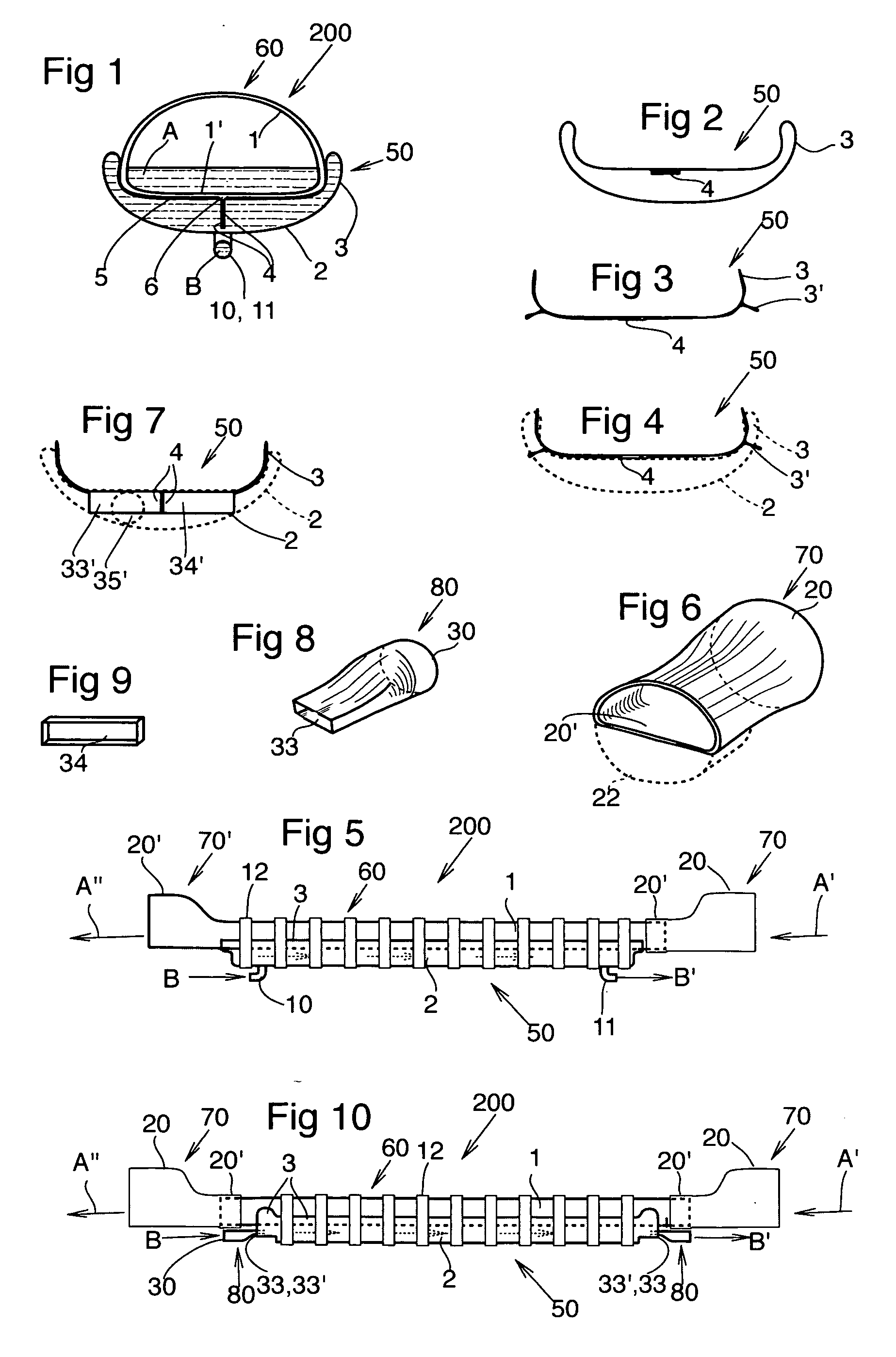
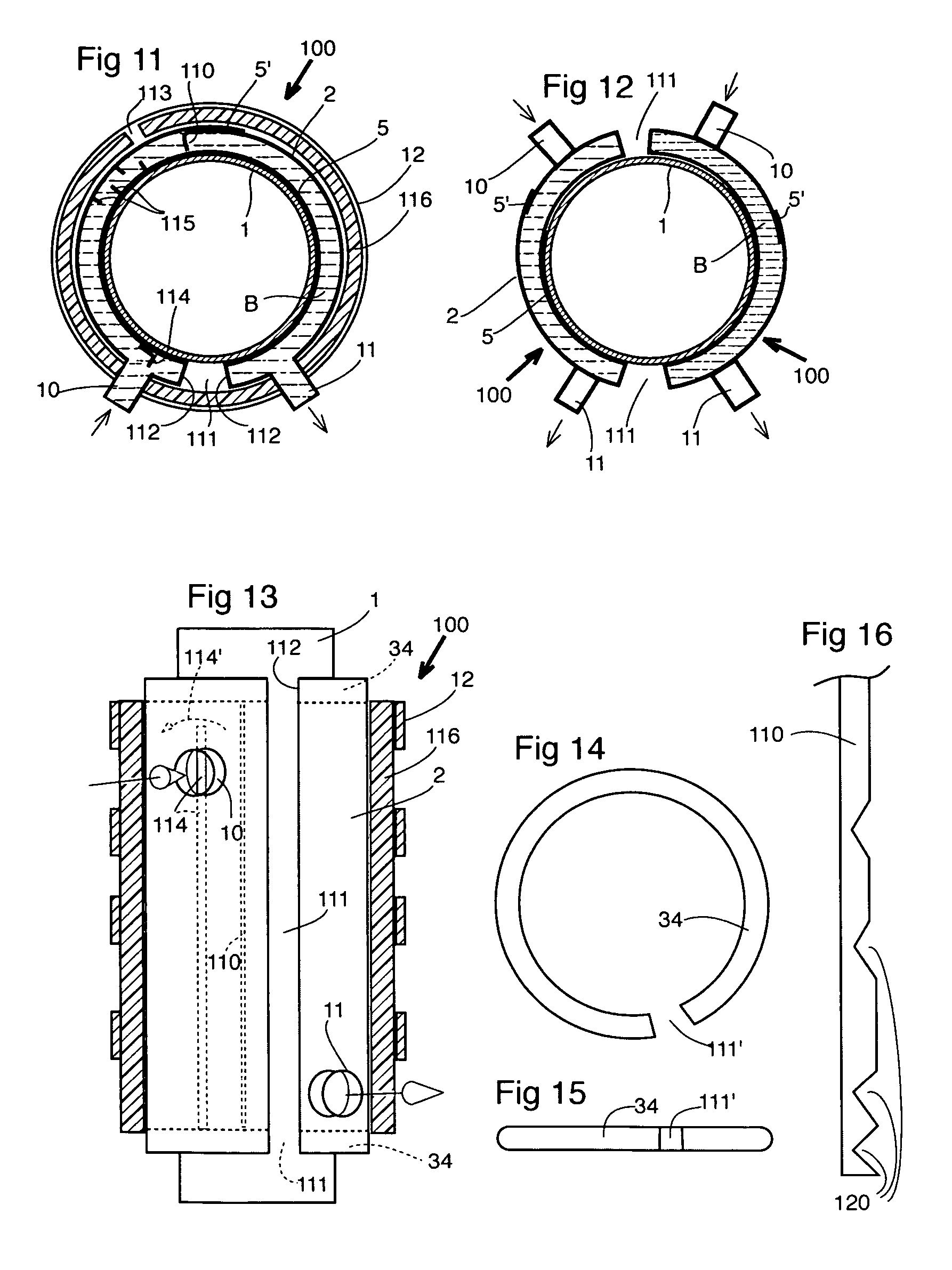
[0044]Two basic embodiments are disclosed, vertical heat exchanger 100, and horizontal heat exchanger 200. each has two conduits in thermal contact. One conduit is a straight pipe or tube that typically carries a waste fluid from which heat is to be recovered, and the second conduit is for the second fluid to which heat is to be transferred, although the heat transfer path could be reversed. Generally the conduits are metal and preferably copper if the temperature differential is small and therefore requires fast heat transfer. The two conduits are co-operatively shaped and tightly clamped together so as to provide optimal thermal contact and thus rapid heat transfer. In the horizontal embodiment the waste conduit is normally on top of the second conduit (waste fluid has heat to be recovered), while in the vertical embodiment the waste conduit is encircled by the second conduit.

[0045]One novel feature of the instant invention is the use of the internal water pressure in the colds wa...


PUM


Abstract

The present invention is a jacket-type heat exchanger which may, for example, be used to replace or fit over a section of drainpipe to heat fresh cold water using the waste heat in the drainwater. Normal cold water pressure is used to create an internal-expanding force on the inner thermal contact wall of the jacket, which, in turn, creates an enormous heat-transfer clamping force on the drainpipe for fast heat transfer. A longitudinal gap in the jacket (or a two-piece jacket) enables clamping movement. An external sleeve with clamps resists bulging of the outer jacket wall. The heated cold water is plumbed to a faucet or water heater so as to reduce hot water use, which, in turn, reduces energy use and related environmental damage. Double-wall construction and venting for visible leak detection satisfies plumbing code requirements. A horizontal embodiment discloses a two-piece plastic-copper drainwater heat exchanger. Use on vehicular exhaust pipes is also contemplated for providing instant interior heat and/or motor warm-up.

Description

[0001]This patent application follows on from provisional application 60 / 998,670.FIELD OF THE INVENTION[0002]A drainpipe heat exchanger for use on drain- or exhaust pipes for waste heat recovery including from any building's drainpipe. It can be made small enough for use with individual plumbing fixtures such as sinks, or for exhaust pipes of cars and trucks. It can also be used over existing drainpipes and exhaust pipes that cannot have their flow interrupted by their temporary removal / replacement. For example large diameter ones are difficult and expensive to remove and reinstall.[0003]Heating cold water to make hot water for cleaning and then discarding the heat along with the dirty hot water is expensive, wasteful and environmentally damaging. It is estimated that in North America some $15 billion dollars is spent annually on fuel to heat water. The fuel's exhaust and the discarded heat in the used hot water contribute doubly to global warming and a lower standard of living. Spe...

Claims


Application Information

Patent Timeline
Patent Type & Authority Applications(United States)
IPC IPC(8): F28D7/00
CPCE03C1/12E03C2001/005F28D7/0008F28D7/0025Y02B30/566F28F9/0246F28F13/00F28F2275/085F28D21/0012Y02B30/56
Inventor MACKELVIE, WINSTON
Owner MACKELVIE WINSTON
Why Eureka
Try Eureka