Light source driving circuit for backlight module

Inactive Publication Date: 2009-04-16
YOUNG LIGHTING TECHNOLOGY INC
View PDF8 Cites 32 Cited by
  • Summary
  • Abstract
  • Description
  • Claims
  • Application Information

AI Technical Summary

Benefits of technology

[0010]Accordingly, the present invention is directed to a light source driving circuit for a backlight module, which employs metal-oxide-semiconductor fie

Problems solved by technology

It is clear from FIG. 1C that when there is no constant-current circuit, the distribution of current of R, G and B corresponding to different light sources are not equal to each other, which makes the luminance of LEDs fail to be controlled and leads to un-equalized luminance and poor display quality.
Although the architecture of the above-mentioned light source driving circuit has an advantage of sim

Method used


Image

  • Light source driving circuit for backlight module
  • Light source driving circuit for backlight module
  • Light source driving circuit for backlight module

Examples


first embodiment

A First Embodiment

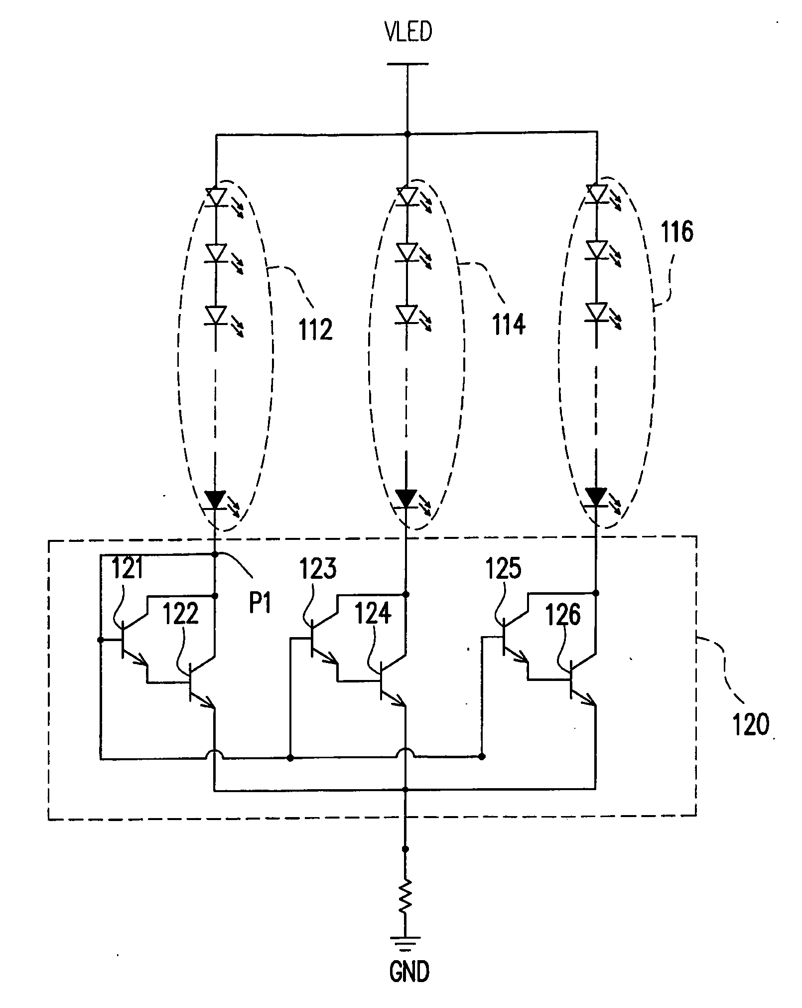
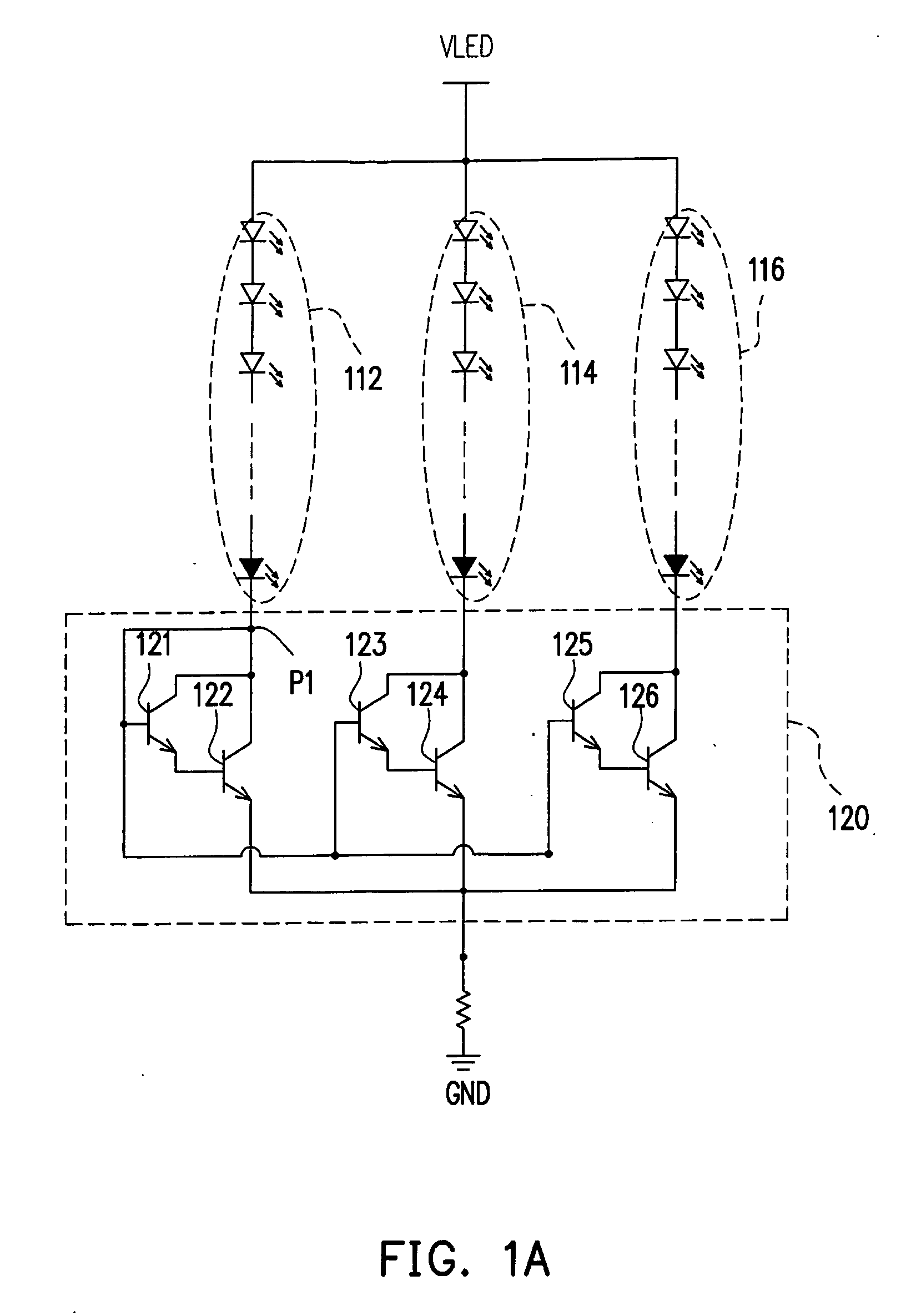
[0037]FIG. 3A is a diagram of a light source driving circuit for a backlight module according to the first embodiment of the present invention. Referring to FIG. 3A, a backlight unit 310 includes multiple LED strings 312, 314 and 316 served as light sources, and a light source driving circuit 320 includes driving units 322, 324 and 326 and a feedback resistor R3. Each of the LED strings 312, 314 and 316 is formed by multiple LEDs in series connection. The anode terminals of the LED strings 312, 314 and 316 are coupled to a voltage source VLED, while the cathode terminals thereof are respectively coupled to the driving units 322, 324 and 326 in the light source driving circuit 320. The light source driving circuit 320 herein is mainly for reducing the differences between the driving currents I1, I2 and I3 passing through the LED strings 312, 314 and 316.

[0038]The driving unit 322 includes a bias resistor R1, a transistor M31, a reference resistor R2 and a shunt regu...

second embodiment

The Second Embodiment

[0046]FIG. 4 is a diagram of a light source driving circuit according to the second embodiment of the present invention. The major difference between FIG. 4 and FIG. 3A rests in that each of the driving units 422, 424 and 426 in a light source driving circuit 420 of FIG. 4 includes an additional capacitor C41, wherein a terminal of C41 is coupled to the first output / input terminal of the transistor M31, while another terminal thereof is coupled to the second output / input terminal of the transistor M31.

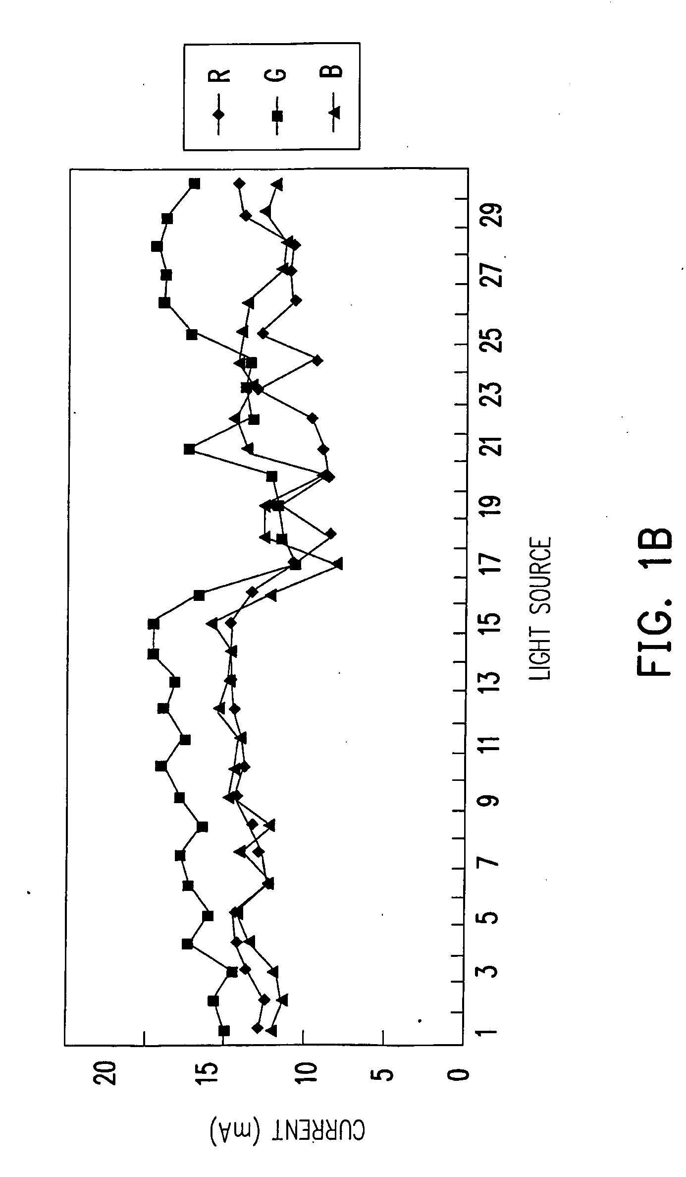
[0047]To obtain different luminance of an LED backlight source, normally, a plurality of LEDs in series connection is used to form an LED string (for example, 312, 314 and 316). However, such a design tends to produce abnormal current waveforms so that the luminance of the LEDs fails to reach the required specification.

[0048]The study of the above problem found that the above-mentioned abnormal current waveforms are caused by unmatched impedances between the capaci...

third embodiment

The Third Embodiment

[0049]FIG. 5 is a diagram of a light source driving circuit with dimming function according to the third embodiment of the present invention. The major difference between FIG. 5 and FIG. 4 rests in that the circuit of FIG. 5 further employs a dimming transistor M51, wherein the third output / input terminal of the dimming transistor M51 is coupled to the common terminal PCOM, the fourth output / input terminal thereof is coupled to the feedback resistor R3 and the control terminal thereof is coupled to a dimming control voltage PWMD. The dimming control voltage PWMD takes pulse width adjustment mode (PWA mode) to affect the time when the dimming transistor M51 is on for adjusting the amounts of the driving currents I1, I2 and I3 to adjust the luminance of the LEDs in the LED strings 312, 314 and 316 and thereby to achieve dimming function. In the embodiment, a light source driving circuit 520 also employs the capacitor C41 to reduce the impact on the driving currents...


PUM


Abstract

A light source driving circuit for a backlight module is disclosed, wherein each driving unit includes a reference resistor, a transistor, a bias resistor and a shunt regulator. The transistor is coupled between an LED string and the reference resistor, and the bias resistor is coupled between an operation voltage and the control terminal of the transistor. The shunt regulator is coupled between the control terminal of the transistor and a common terminal, and the reference pin of the shunt regulator is coupled to the common node between the reference resistor and the transistor.

Description

CROSS-REFERENCE TO RELATED APPLICATION[0001]This application claims the priority benefit of Taiwan application serial no. 96138498, filed on Oct. 15, 2007. The entirety of the above-mentioned patent application is hereby incorporated by reference herein and made a part of this specification.BACKGROUND OF THE INVENTION[0002]1. Field of the Invention[0003]The present invention generally relates to a light source driving circuit for a backlight module, and more particularly, to a light source driving circuit for a backlight module employing light emitting diodes (LEDs) as the light source thereof.[0004]2. Description of Related Art[0005]FIG. 1A is a diagram of a conventional light source driving circuit. A light source driving circuit 120 is for driving multiple light emitting diode strings (LEDs strings) 112, 114 and 116, each of which is composed of multiple LEDs. The light source driving circuit 120 is coupled to the cathode terminals of the LED strings 112, 114 and 116 for controll...

Claims


Application Information

Patent Timeline
IPC IPC(8): G09G3/36
CPCG09G3/342G09G2320/0233H05B33/0827G09G2330/02G09G2320/0633H05B45/46
Inventor LAN, YU-CHINCHANG, HUI - CHIHSIAO, CHIEN-CHUNG
Owner YOUNG LIGHTING TECHNOLOGY INC
Why Eureka
Try Eureka