Shaping a laser beam with a fiber-based device

a fiber-based device and laser beam technology, applied in the direction of laser optical devices, optical light guides, optics, etc., can solve the problems of incompatibility with single-mode fiber use, power loss generation, and power loss at the operative surface of the optical components, so as to reduce the field intensity, enhance the field intensity, and increase the beam size

Inactive Publication Date: 2009-04-16
GU XIJIA +1
View PDF2 Cites 15 Cited by
  • Summary
  • Abstract
  • Description
  • Claims
  • Application Information

AI Technical Summary

Benefits of technology

[0004]In one aspect, the invention provides a method of applying a laser beam to an object in which the laser beam has an initial intensity distribution of Gaussian shape and a final intensity distribution of predetermined shape at a surface of the object. The method involves guiding the laser beam along a single mode fiber from an input end of the fiber toward an output end of the fiber, the fiber comprising a core in which the laser beam is guided and a cladding that surrounds the core. A portion of the guided beam is coupled from the core into the cladding for propagation along the cladding toward the output end of the fiber. This is preferably achieved with a long-period grating (“LPG”) installed inline with the fiber, which may typically be adapted to couple the single transmission mode of the core to a lower order cladding mode. The surface of the object is placed at a position spaced from the output end of the fiber where interaction between core and cladding propagation modes produces the final intensity distribution. Although a single LPG can be used for such purposes, multiple components may be used to couple the single mode of the core to varying degrees into different cladding modes, allowing greater freedom in shaping the laser beam. As will be demonstrated below, it is possible to produce useful approximations of a uniform intensity distribution, a ring-shaped distribution and others.
[0007]Coupling the core mode LP01 into a low-order cladding mode LP0m effectively enlarges the beam size since a Gaussian distribution is converted into a series of larger concentric rings with m nodes. The lower-order LP0m modes can propagate a long distance with negligible modal distortion or coupling into higher order LP1m modes, as has been demonstrated [6]. If only part of the core mode is coupled into a cladding mode, the two modes will interfere. Because of their different propagation constants, the interference pattern will vary as the modes propagate along the fiber and through free space at the end of the fiber. Since destructive interference can lead to reduced field intensity at the centre of the beam and enhanced field intensity in the first or second ring of the cladding mode, it is possible to achieve an approximation to a beam of uniform intensity.

Problems solved by technology

Moreover, reflection at operative surfaces of the optical components can be expected to introduce power losses unless anti-reflective coatings adapted to accommodate high laser power are used.
Beam uniformity was not, however, detailed.
Additionally, these approaches are incompatible with use of single mode fibers, and do not lend themselves to production of other useful intensity distributions, such as ring-shaped distributions.

Method used


Image

  • Shaping a laser beam with a fiber-based device
  • Shaping a laser beam with a fiber-based device
  • Shaping a laser beam with a fiber-based device

Examples


Embodiment Construction

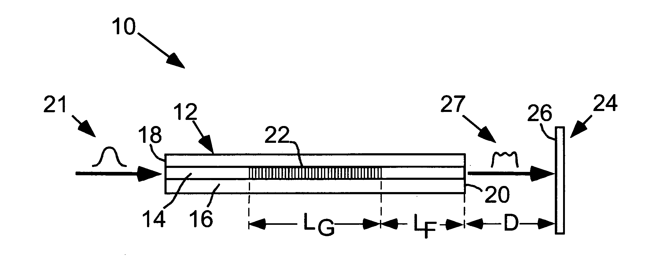
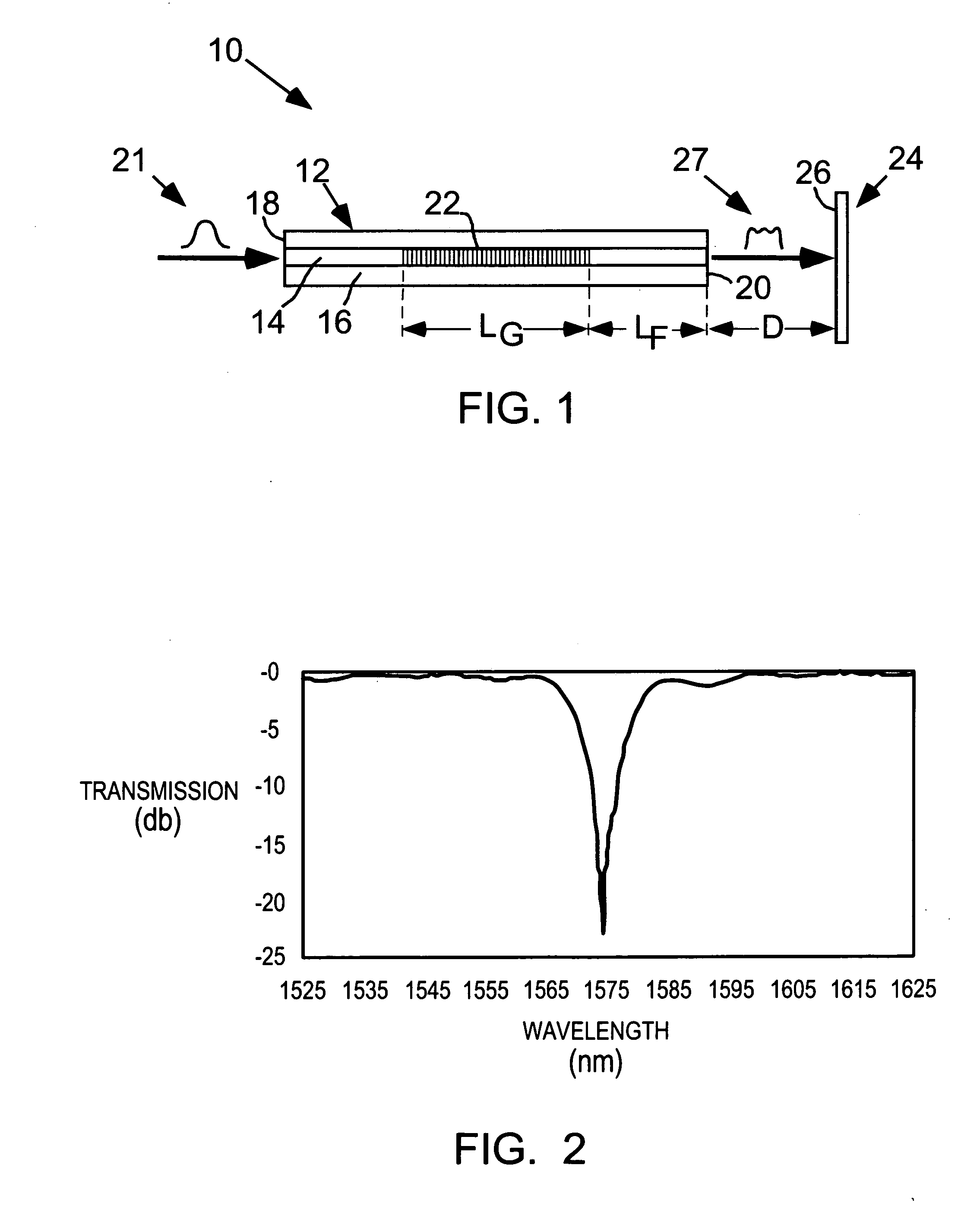
[0019]Reference is made to FIG. 1, which schematically illustrates a prototype fiber-based device 10 that effectively converts a Gaussian shaped beam into a beam of substantially uniform intensity. The device 10 comprises a single mode fiber 12 with a core 14, a cladding 16 surrounding the core 14, an input end 18, and an output end 20. The input end 18 receives a laser beam from a tunable laser (not shown) operating in the near infrared range, which beam has a typical Gaussian intensity profile 21. The laser beam is guided within the core 14 toward the output end 20 of the fiber 12. The device 10 also comprises an LPG 22 inscribed inline with the core 14 of the fiber 12 upstream of the output end 20 of the fiber 12, which LPG 22 couples a portion of the light guided in the core 14 into the cladding 16 for forward propagation toward the output end 20. In this embodiment, the core mode is coupled to the LP03 cladding mode. The LPG 22 has a length designated LG and is spaced a distanc...


PUM


Abstract

A fiber-based device and associated method effectively convert a laser beam with an initial intensity distribution of Gaussian shape into a beam with another intensity distribution, which might typically be uniform or ring-shaped although other configurations are possible. The device comprises a single mode fiber with a core in which the beam is guided and a cladding surrounding the core. A component inline with the fiber couples a portion of the guided beam from the core into the cladding for propagation through the cladding toward an output end of the fiber. Interaction between core and cladding propagation modes produces the other intensity distribution at a predetermined distance from the output end of the fiber.

Description

FIELD OF THE INVENTION[0001]The invention relates generally to shaping of laser beams, and more specifically, to conversion of a laser beam with a Gaussian intensity distribution effectively into a beam with another intensity distribution. Substantially uniform and ring-shaped intensity distributions are of primary interest but other distributions can be achieved with the invention.DESCRIPTION OF THE PRIOR ART[0002]The Gaussian-shaped laser beam typically produced by a laser is satisfactory for applications that involve cutting or marking. However, other applications such as laser lithography or medical treatment require a beam with a substantially uniform intensity profile often referred to as a “top-hat” profile. It is known to use diffractive optical components to bend a Gaussian-shaped distribution of rays to approximate a beam of uniform intensity [1]. (References to technical publications are identified with numbers in square brackets and are detailed below after the descripti...

Claims


Application Information

Patent Timeline
Patent Type & Authority Applications(United States)
IPC IPC(8): G02B6/02
CPCG02B6/02095G02B6/14H01S3/005G02B27/0994G02B27/0927
Inventor GU, XIJIASOLIMAN, WALEED SOLIMAN MOHAMMED
Owner GU XIJIA
Why Eureka
Try Eureka