Active damping of wind turbine blades

a technology of active damping and wind turbine blades, which is applied in the direction of rotors, electric generator control, vessel construction, etc., can solve the problems of more drag, more noise-causing turbulence, and wind turbine noise still a major obstacle to implementation

Inactive Publication Date: 2009-04-16
GENERAL ELECTRIC CO
View PDF14 Cites 75 Cited by
  • Summary
  • Abstract
  • Description
  • Claims
  • Application Information

AI Technical Summary

Benefits of technology

[0009]These and other aspects of such conventional approaches are addressed here by providing, in various embodiments, a wind turbine blade including a sensor, arranged upstream from a trailing edge of the blade, for measuring an airflow characteristic near a surface of the blade; and an actuator, arranged downstream from the sensor, for adjusting the blade in response to the measured airflow characteristic. Also disclosed here is a wind generator, including a tower supporting a drive train with a rotor; at least one blade extending radially from the rotor; means, arranged upstream from a trailing edge of the blade, for sensing an airflow characteristic near a surface of the blade; means, arranged downstream from the sensing means, for actuating a portion of the blade in response to the sensed airflow characteristic; and means for regulating the actuating means in response to a signal from the sensing means. In another embodiment, the technology disclosed here relates to a method of reducing noise from a wind turbine blade, including sensing an airflow characteristic at location near a surface of the blade upstream from a trailing edge of the blade; and actuating a portion of the blade downstream from the sensing location in response to the sense airflow characteristic.

Problems solved by technology

Although wind energy is one of the fastest growing sources of renewable energy, wind turbine noise is still a major obstacle to implementation.
For large, modern wind turbines, aerodynamic noise is considered to be the dominant source of this noise problem, and, in particular, so-called “trailing edge noise” caused by the interaction of turbulence in the boundary layer with the trailing edge of the blade.
This transition point tends to move forward on the chord of the blade 10 as the speed and angle of attack of the blade increases, resulting in more drag and more noise-causing turbulence.

Method used


Image

  • Active damping of wind turbine blades
  • Active damping of wind turbine blades
  • Active damping of wind turbine blades

Examples


Embodiment Construction

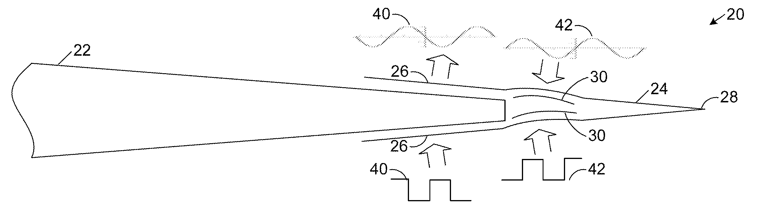
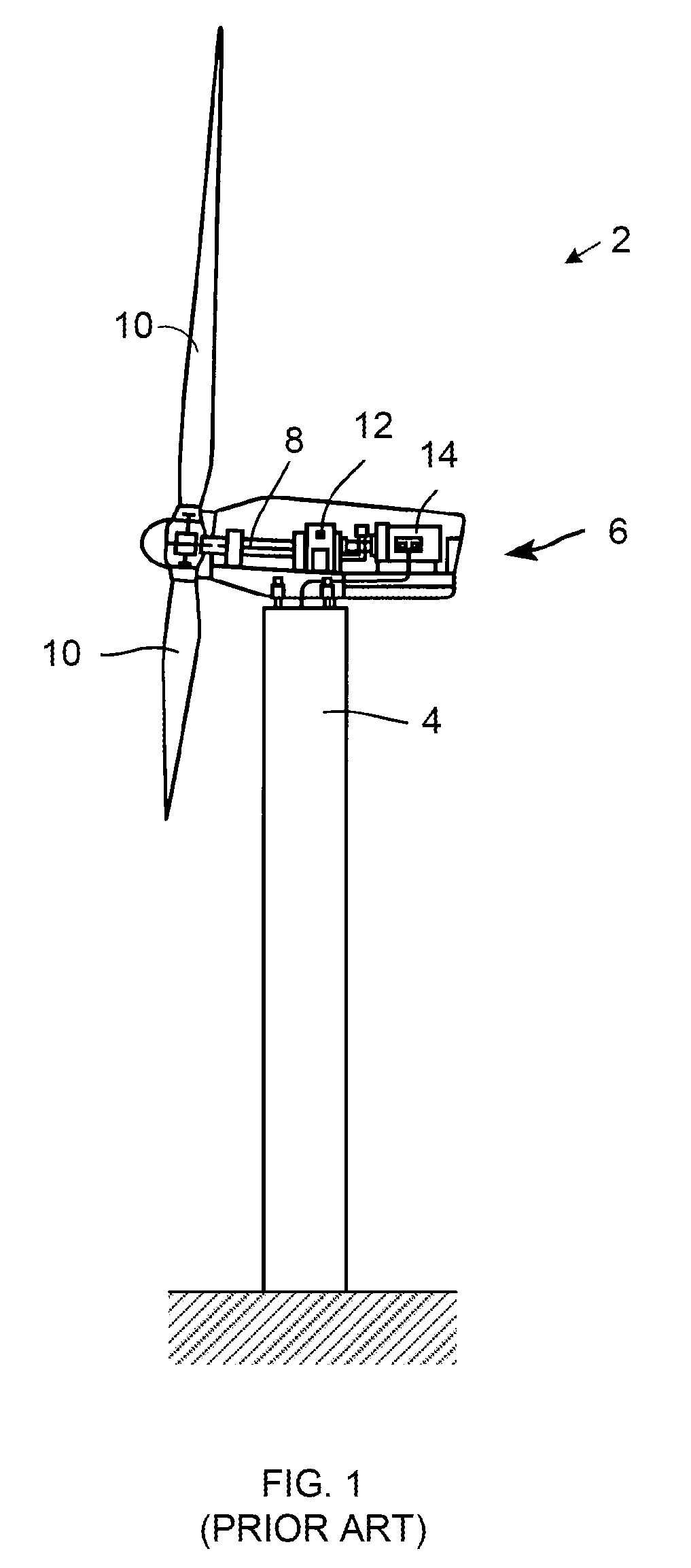
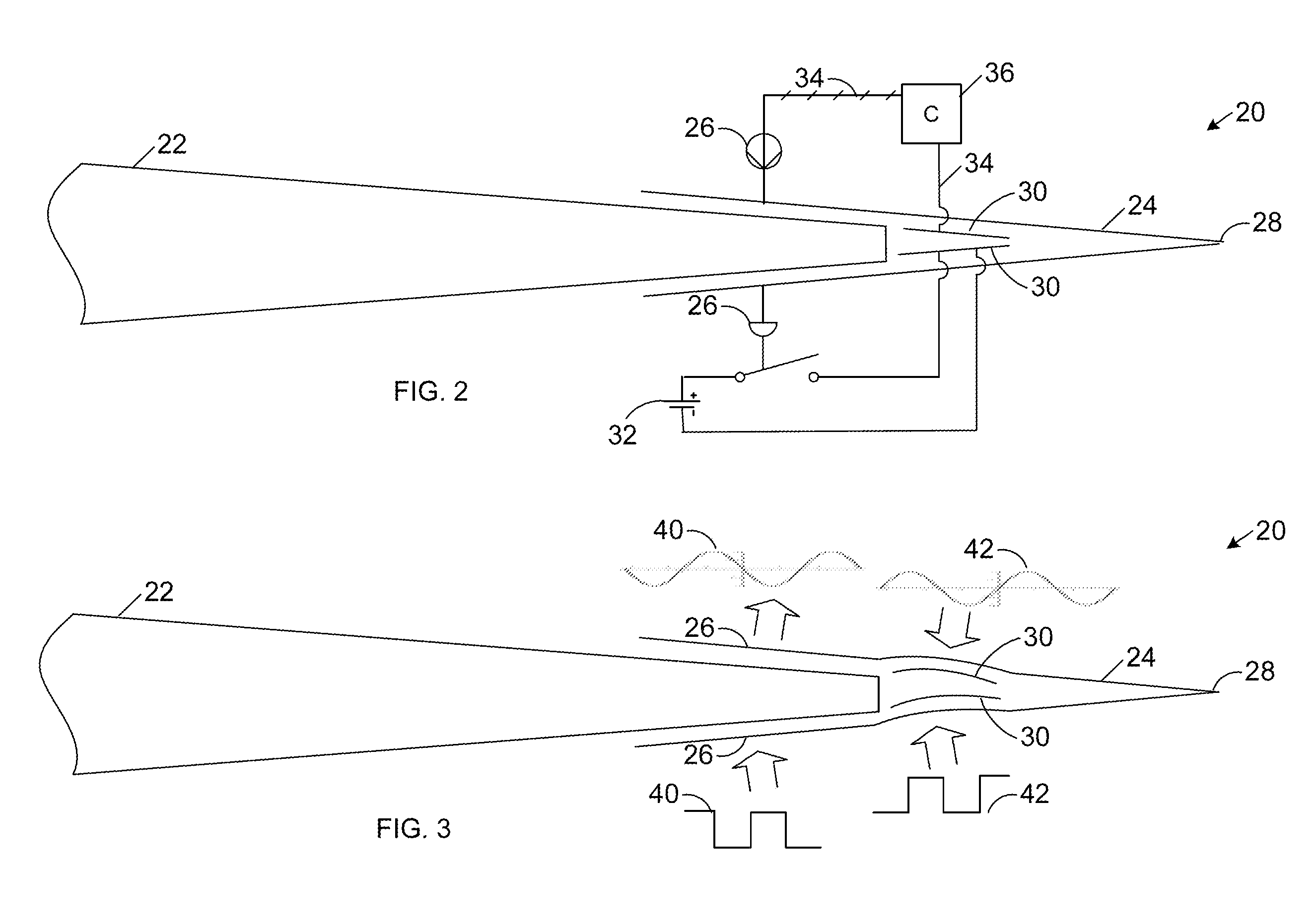
[0014]FIGS. 2 and 3 are schematic, partial cross-sectional view of a wind turbine blade 20 for use with the wind generator shown in FIG. 1, or any other wind turbine. For example, the blade 20 illustrated in FIG. 2 may replace any and / or all of the conventional blades 10 illustrated in FIG. 1. In the illustrated examples, the turbine blade 20 includes a main body 22 and a trailing edge cap 24 as disclosed in copending U.S. patent application Ser. No. 11 / 193,696 (Attorney Docket No. 167650). corresponding to Patent Publication No. 2007 / 0025858. However, the technology discussed below may also be applied in a variety of other configurations, including, but not limited to directly to the main body 22 of the blade 20, without the trailing edge cap 24.

[0015]In the illustrated examples, the blade 20 includes a sensor 26 arranged upstream from a trailing edge 28 of the blade 20, opposite from the direction of airflow over the corresponding surface of the blade, for measuring an airflow cha...


PUM


Abstract

A wind turbine blade, includes a sensor, arranged upstream from a trailing edge of the blade for measuring an airflow characteristic near a surface of the blade; and an actuator, arranged downstream from the sensor, for adjusting the airflow in response to the measured characteristic.

Description

BACKGROUND OF THE INVENTION[0001]1. Technical Field[0002]The subject matter described here generally relates to fluid reaction surfaces with vibration damping features, and, more particularly to active damping for wind turbine blade noise and / or drag reduction.[0003]2. Related Art[0004]A wind turbine is a machine for converting the kinetic energy in wind into mechanical energy. If that mechanical energy is used directly by machinery, such as to pump water or to grind wheat, then the wind turbine may be referred to as a windmill. Similarly, if the mechanical energy is further transformed into electrical energy, then the turbine may be referred to as a wind generator or wind power plant.[0005]Wind turbines use one or more airfoils in the form of a “blade” to generate lift and capture momentum from moving air that is them imparted to a rotor. Each blade is typically secured at its “root” end, and then “spans” radially “outboard” to a free, “tip” end. The front, or “leading edge,” of th...

Claims


Application Information

Patent Timeline
Patent Type & Authority Applications(United States)
IPC IPC(8): F03D7/00F01D5/14F03D9/00
CPCF05B2260/96Y02E10/721F05B2270/324F03D7/022Y02E10/723Y02E10/72
Inventor DRIVER, HOWARD D.HERR, STEFANKINZIE, KEVIN W.
Owner GENERAL ELECTRIC CO
Why Eureka
Try Eureka