Serpentine microcircuit cooling with pressure side features
- Summary
- Abstract
- Description
- Claims
- Application Information
AI Technical Summary
Benefits of technology
Problems solved by technology
Method used
Image
Examples
Embodiment Construction
)
[0023]Referring now to FIG. 5, there is shown an airfoil portion 30 of a turbine engine component. The turbine engine component may comprise a turbine blade or any other component having an airfoil portion.
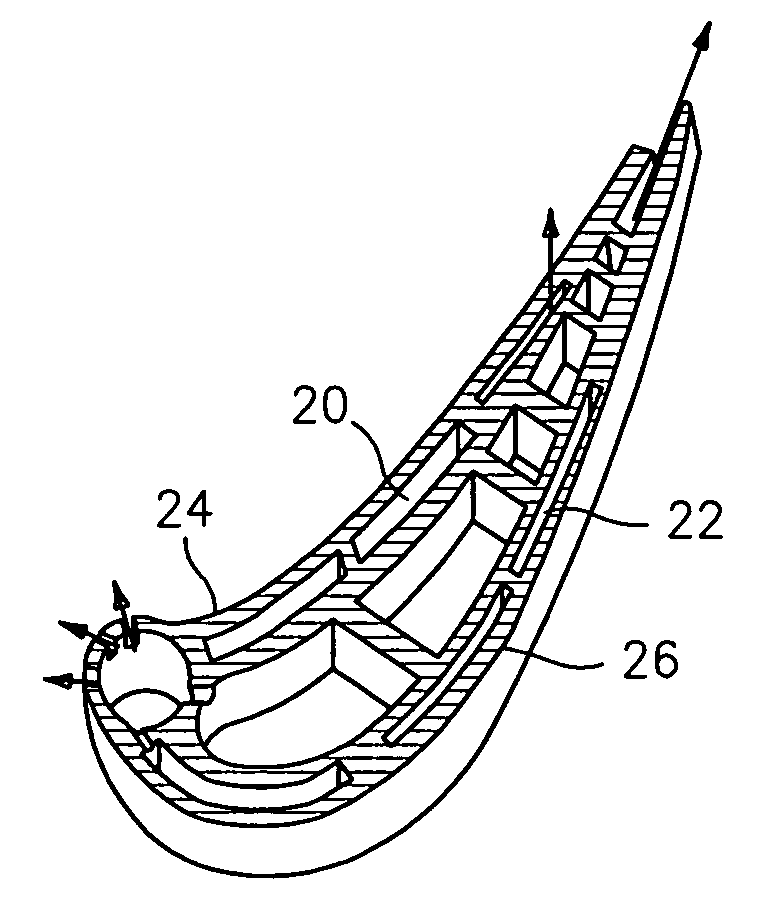
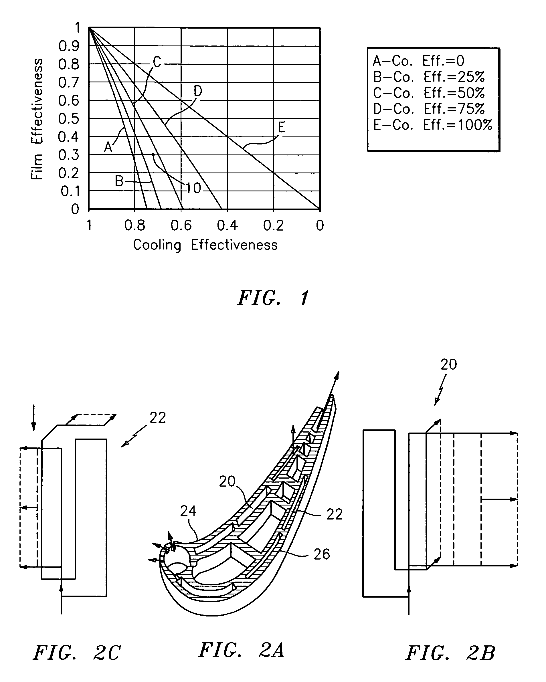
[0024]The airfoil portion 30 has a pressure side 32 formed by a pressure side wall 34 and a suction side 36 formed by a suction side wall 38. The airfoil portion 30 further has a plurality of internal cavities 40 through which a cooling fluid flows. Embedded in the pressure side wall 34 is a serpentine cooling microcircuit 42. Embedded in the suction side wall 38 is a serpentine cooling microcircuit 44.
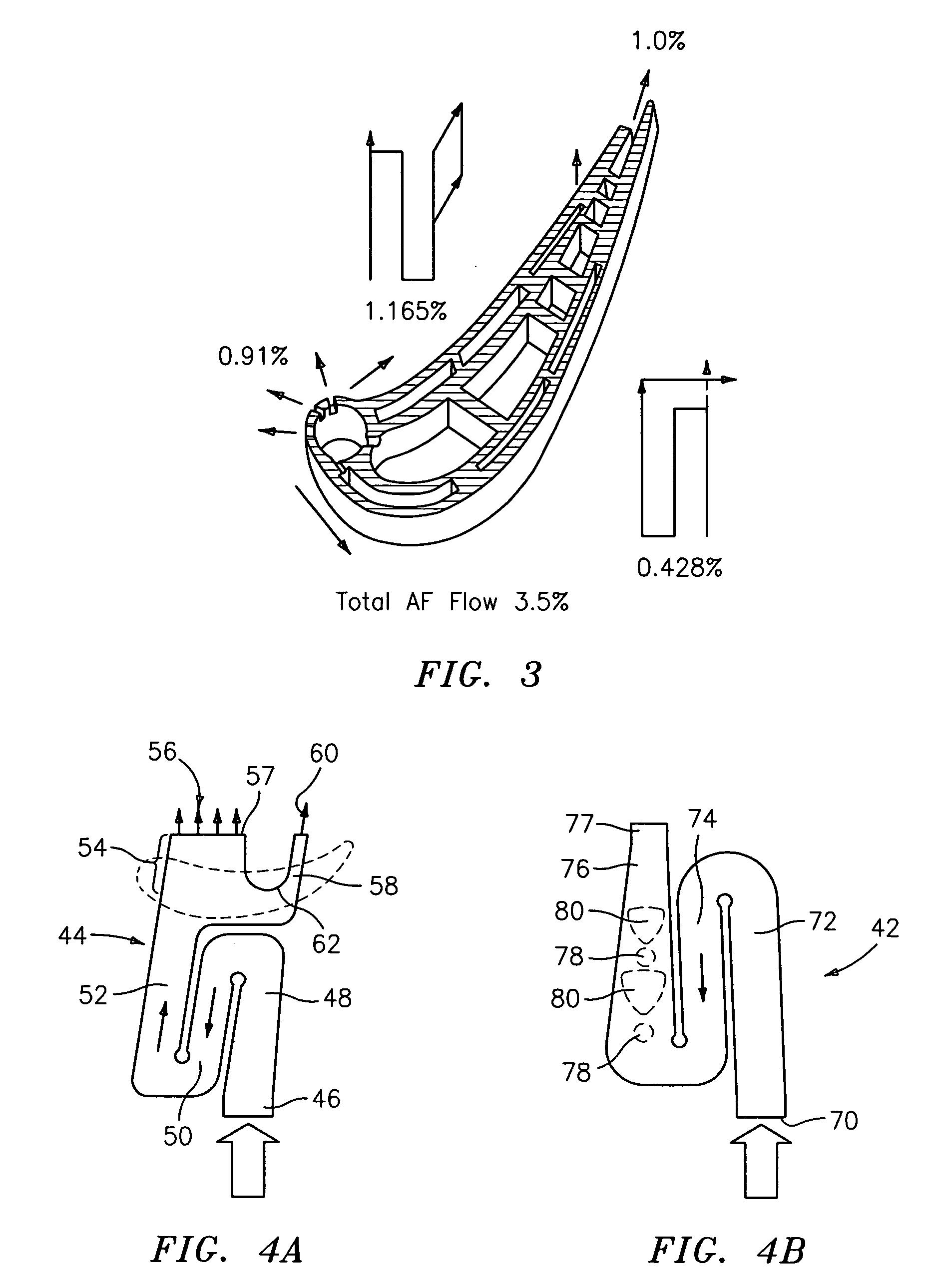
[0025]Referring now to FIG. 4A, there is shown a schematic representation of the serpentine cooling microcircuit 44. The serpentine cooling microcircuit 44 includes an inlet 46 which communicates with one of the internal cavities 40. The microcircuit 44 further includes an inlet leg 48, an intermediate leg 50, and outlet leg 52. The outlet leg 52 has a first portion 54 with a plura...
PUM
 Abstract
Description
Claims
Application Information
 - R&D
- Intellectual Property
- Life Sciences
- Materials
- Tech Scout
- Unparalleled Data Quality
- Higher Quality Content
- 60% Fewer Hallucinations
Browse by: Latest US Patents, China's latest patents, Technical Efficacy Thesaurus, Application Domain, Technology Topic, Popular Technical Reports.
© 2025 PatSnap. All rights reserved.Legal|Privacy policy|Modern Slavery Act Transparency Statement|Sitemap|About US| Contact US: help@patsnap.com


