Composite Heat Shield

a heat shield and composite technology, applied in the field of heat shields, can solve the problems of increased brake wear, increased fuel consumption, increased weight, etc., and achieve the effect of reducing or eliminating the need for additional heat barriers and simple construction

Active Publication Date: 2009-04-16
THE BOEING CO
View PDF12 Cites 22 Cited by
  • Summary
  • Abstract
  • Description
  • Claims
  • Application Information

AI Technical Summary

Benefits of technology

[0005]Therefore, a heat shield is needed which is simple in construction, is effective in protecting airc...

Problems solved by technology

Therefore, in order to maintain the idle exhaust temperature at a temperature level which is lower than the heat capacity of titanium, the engine may require operation at a higher thrust with a resulting higher fuel consumption level.
This may result in an increased lev...

Method used


Image

  • Composite Heat Shield
  • Composite Heat Shield
  • Composite Heat Shield

Examples


Embodiment Construction

[0021]The disclosure is generally directed to a composite matrix ceramic (CMC) heat shield lower surface which may have a heat capacity higher than that of titanium. The ceramic heat shield may provide a one-piece (no segmented gaps) construction which may undergo minimal thermal expansion during aircraft engine thermal cycling and may have a high temperature capacity to thermally isolate structure and systems above the heat shield from engine exhaust on an aircraft. Consequently, an aircraft engine on which the heat shield is assembled may be operated at a lower idle thrust and higher temperature, resulting in decreased fuel consumption and brake wear.

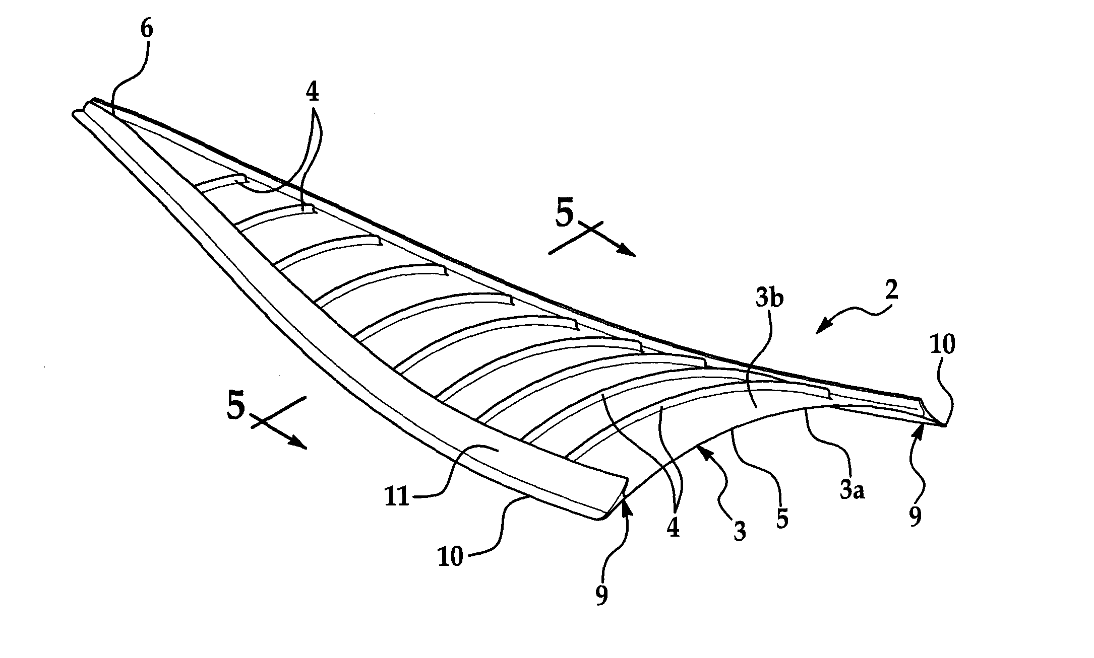
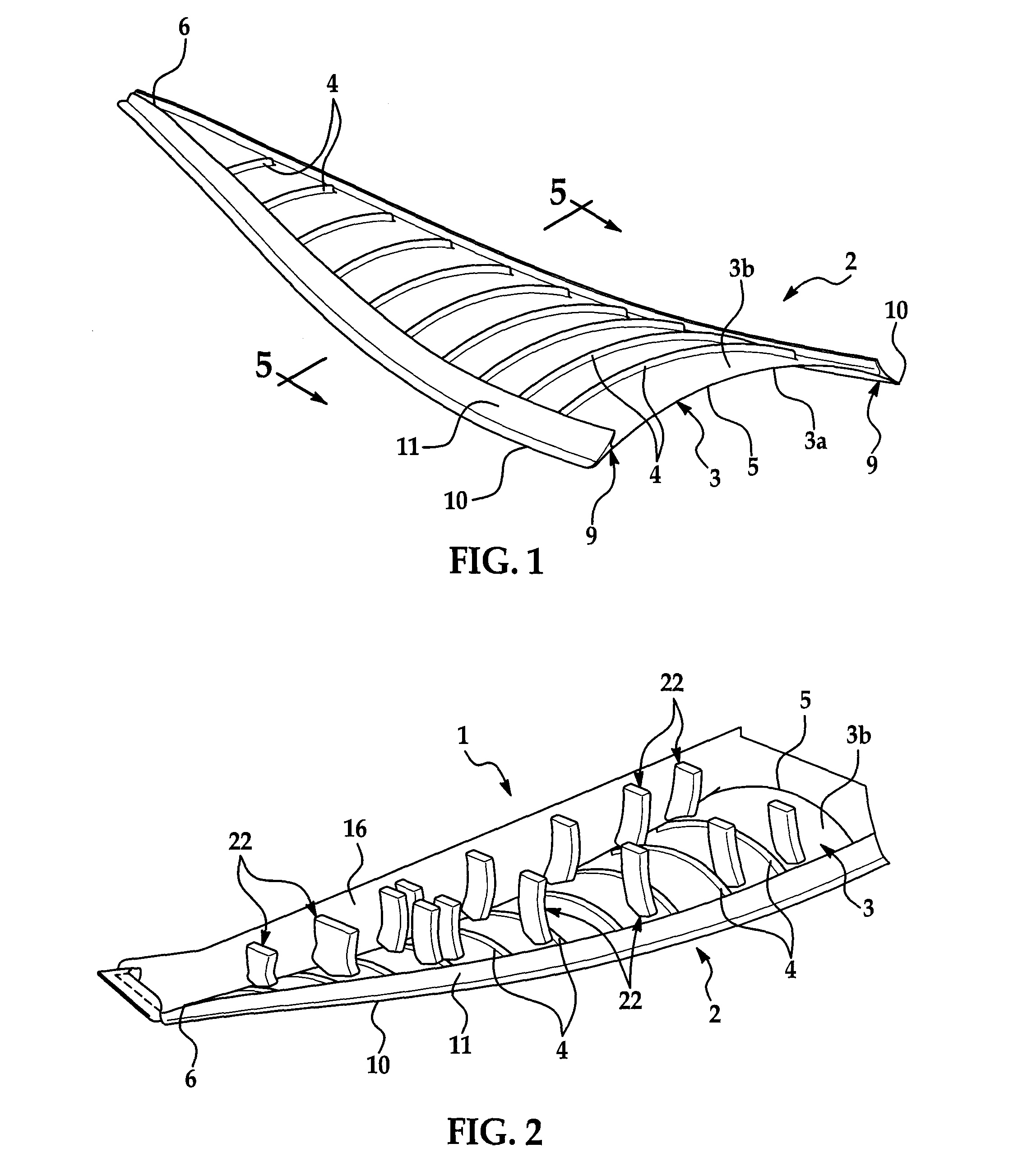
[0022]Referring initially to FIGS. 1 and 5-7, an illustrative embodiment of the heat shield is generally indicated by reference numeral 2. The heat shield 2 may include a heat shield panel 3 which may include a wide panel end 5 and a narrow panel end 6 and have a generally elongated, conical shape when viewed from above or below. The ...


PUM

PropertyMeasurementUnit
Shapeaaaaaaaaaa

Abstract

A composite heat shield includes a ceramic composite heat shield body comprising a pair of generally spaced-apart heat shield side panels, a heat shield bottom panel extending between the heat shield side panels and having a heat exposure surface, a heat shield top panel extending between the heat shield side panels in spaced-apart relationship with respect to the heat shield bottom panel and having at least one heat shield surface and at least one heat shield cavity defined between the heat shield bottom panel and the heat shield top panel.

Description

CROSS-REFERENCE TO RELATED APPLICATIONS[0001]This application is a continuation-in-part of application Ser. No. 11 / 870,513, filed Oct. 11, 2007 and entitled “Ceramic Heat Shield”.TECHNICAL FIELD OF THE INVENTION[0002]The disclosure relates generally to heat shields. More particularly, the disclosure relates to a composite heat shield and thermal barrier which is suitable for aircraft.BACKGROUND OF THE INVENTION[0003]Existing aircraft heat shields may be made from titanium, which has an upper temperature limit of about 1100 degrees F. Multiple segments may be built into the titanium heat shield to facilitate thermal expansion and contraction. Aircraft engines may be designed to operate more efficiently by running at idle exhaust temperatures which are higher than the heat capacity of titanium. Therefore, in order to maintain the idle exhaust temperature at a temperature level which is lower than the heat capacity of titanium, the engine may require operation at a higher thrust with a...

Claims


Application Information

Patent Timeline
IPC IPC(8): B32B3/10
CPCB64D33/04B64G1/58B64C7/02B64D29/02Y10T428/234Y10T428/1314Y10T428/24562Y10T428/24661Y10T428/1317
Inventor ZIELINSKI, EDWARDCONNELLY, THOMAS J.
Owner THE BOEING CO
Why Eureka
Try Eureka