Software and Methods for Dental Treatment Planning

a technology of dental treatment and software, applied in the field of orthodontics, can solve the problems of difficult to see the relation between the facing surfaces of the opposite teeth of the upper and lower jaws, difficult to see if the affected tooth affects the occlusion, and inability to achieve the goal

Active Publication Date: 2009-04-16
ORMCO CORP
View PDF47 Cites 102 Cited by
  • Summary
  • Abstract
  • Description
  • Claims
  • Application Information

AI Technical Summary

Benefits of technology

[0021]Certain aspects of the following invention solve these and other problems by providing a software modeling tool capable of manipulating the digital images of the teeth from their original position as digitized and scanned to an optimal position. The tool allows the treating orthodontist to develop a treatment plan based on evaluating tooth movements in the modeling tool.

Problems solved by technology

This approach, however, has a number of major drawbacks.
First, in the occluded state it is difficult to see the relation between facing surfaces of opposite teeth of the upper and lower jaws.
Second, on moving a tooth, or adding a tooth, or changing the form of a tooth in the dental model, it is not easy to see if the affected tooth affects the occlusion.
Third, the information provided by dental models regarding proximity of opposite teeth in opposite jaws is typically no more than whether certain points of opposite teeth make contact, or not, in the occluded state.
Achieving this objective has been inhibited by certain problems in the prior art.
One problem presented by the prior art is that current orthodontic products are designed and manufactured to average anatomy.
Some of this modification may be performed when the appliance is initially installed, but almost inevitably modification is required during the course of treatment of the patient.
Thus, the treatment of the patient has become a manual feedback system in which the orthodontist monitors the progress of the patient's treatment and then readjusts the appliance, usually by bending the arch wires, to correct the forces being applied to the teeth to bring the teeth to their ultimate positions, which are less than ideal.
In addition, the time required of the orthodontist for implementation of the treatment may be several times greater than it would be if modification of the appliance were unnecessary.
Thus, the orthodontist is able to treat fewer patients and the cost of the treatment to the patient or to the orthodontist is increased.
Location of the connection points for the appliance to the teeth also presents a problem in the prior art.
If they are placed to close to the tips of the teeth, however, they may interfere with the teeth of the opposite arch as the teeth approach their finish positions.
Another problem of the prior art that has inhibited the selection or design of an ideal orthodontic appliance for the patient is the difficulty in arriving at an expression of the ideal finish position of the teeth.
This process is time consuming and presents a source of error and inaccuracy.
In reality, the treatment of patients is in many cases more of an art than a science, with results ranging from, poor to excellent, and generally variable.
The development of automated custom appliance design systems has encountered several difficulties.
These difficulties have included the task of developing an automated system that includes reliable and efficient decision making algorithms and techniques for automatically determining an ideal finish position of the teeth.
Further, these difficulties have included arriving at an expression of appliance geometry in terms that can be efficiently produced by automated appliance manufacturing equipment.
Furthermore, the prior art has not provided a way to accurately manufacture an appliance on an individualized basis in accordance with the appliance design.
An additional problem in the automated design and manufacture of orthodontic appliances lies in the difficulty in designing the custom design system to take into account the professionally recognized parameters and criteria, derived over many years from the knowledge and experience of the practicing and clinical orthodontist, upon which diagnosis and treatment is based.
However, none of the existing virtual computer dental models provide tools relating to the distance between opposite teeth on opposite jaws.

Method used


Image

  • Software and Methods for Dental Treatment Planning
  • Software and Methods for Dental Treatment Planning
  • Software and Methods for Dental Treatment Planning

Examples


Embodiment Construction

[0063]Systems and methods that use computers to model a patient's teeth and to design orthodontic treatment and appliances have been proposed by applicant, examples of which are disclosed in International Applications Nos. PCT / US2003 / 030917, filed on Sep. 26, 2003, and International Patent Application No. PCT / US00 / 35558, filed Dec. 29, 2000, both hereby expressly incorporated herein by reference in their entireties. Typical systems of these types provide an interface through which a treating orthodontist or others can communicate treatment and design preferences and data. The present invention provides enhancements to such systems that improve the functionality and utility of such systems, as set forth herein.

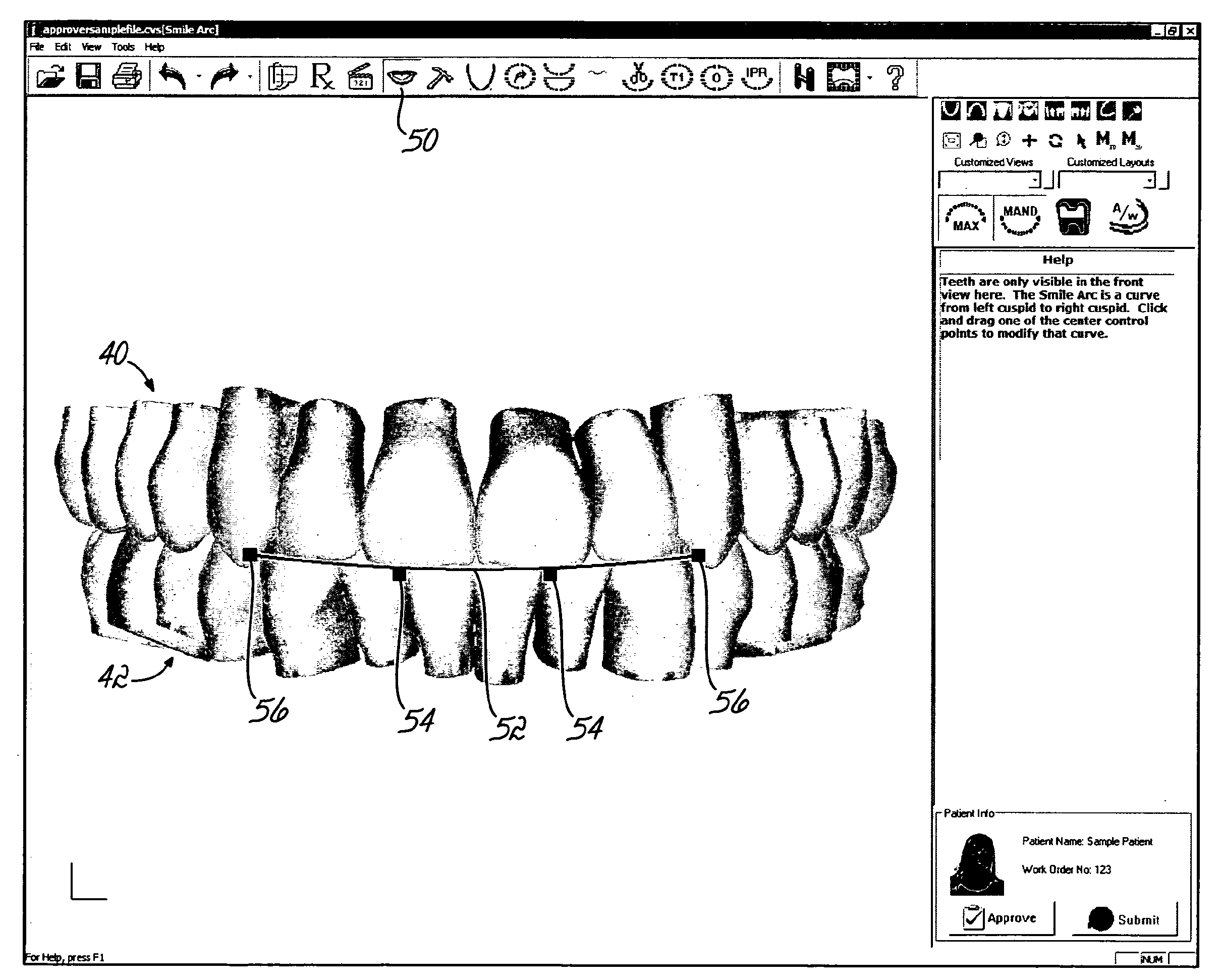
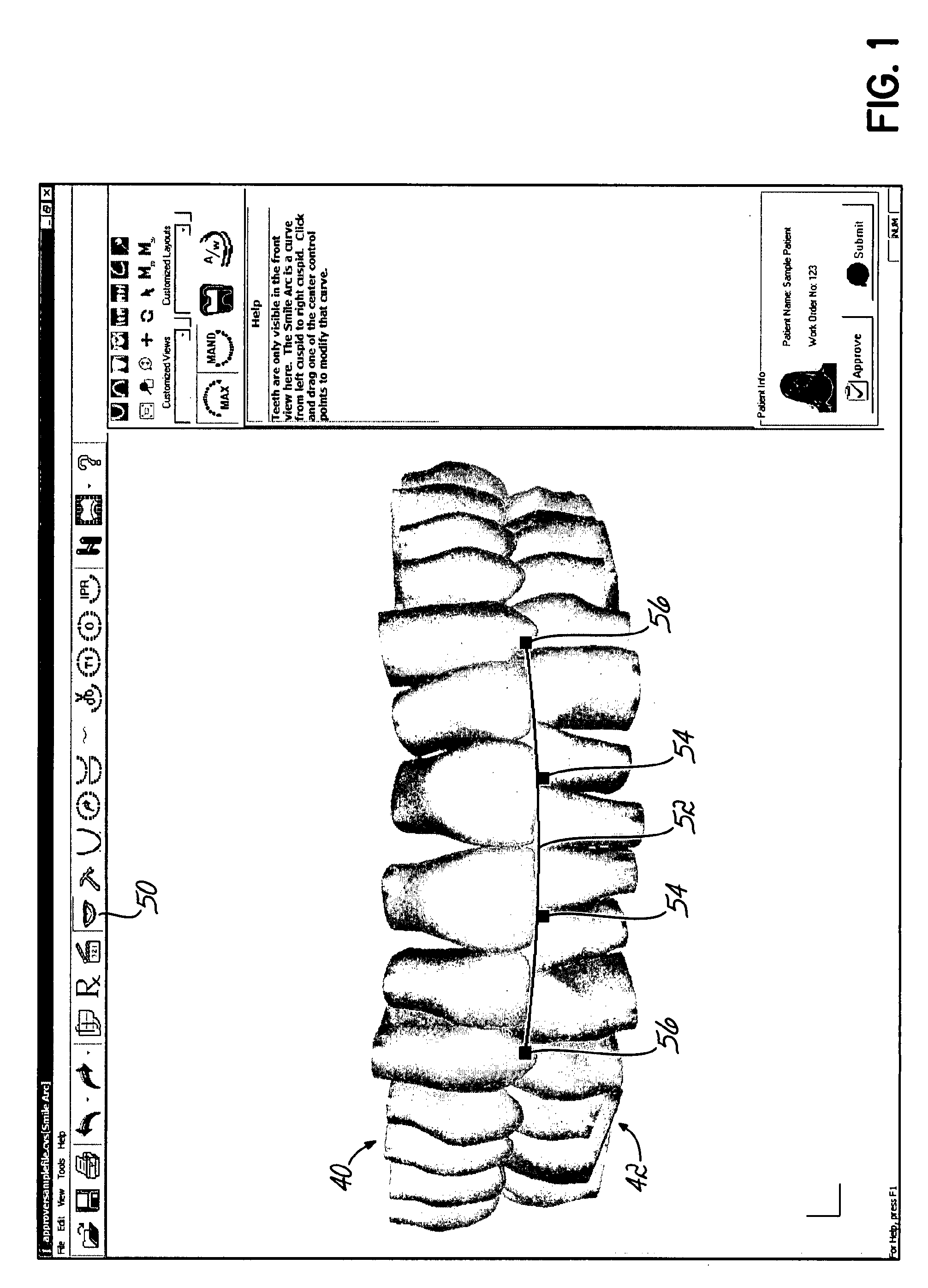
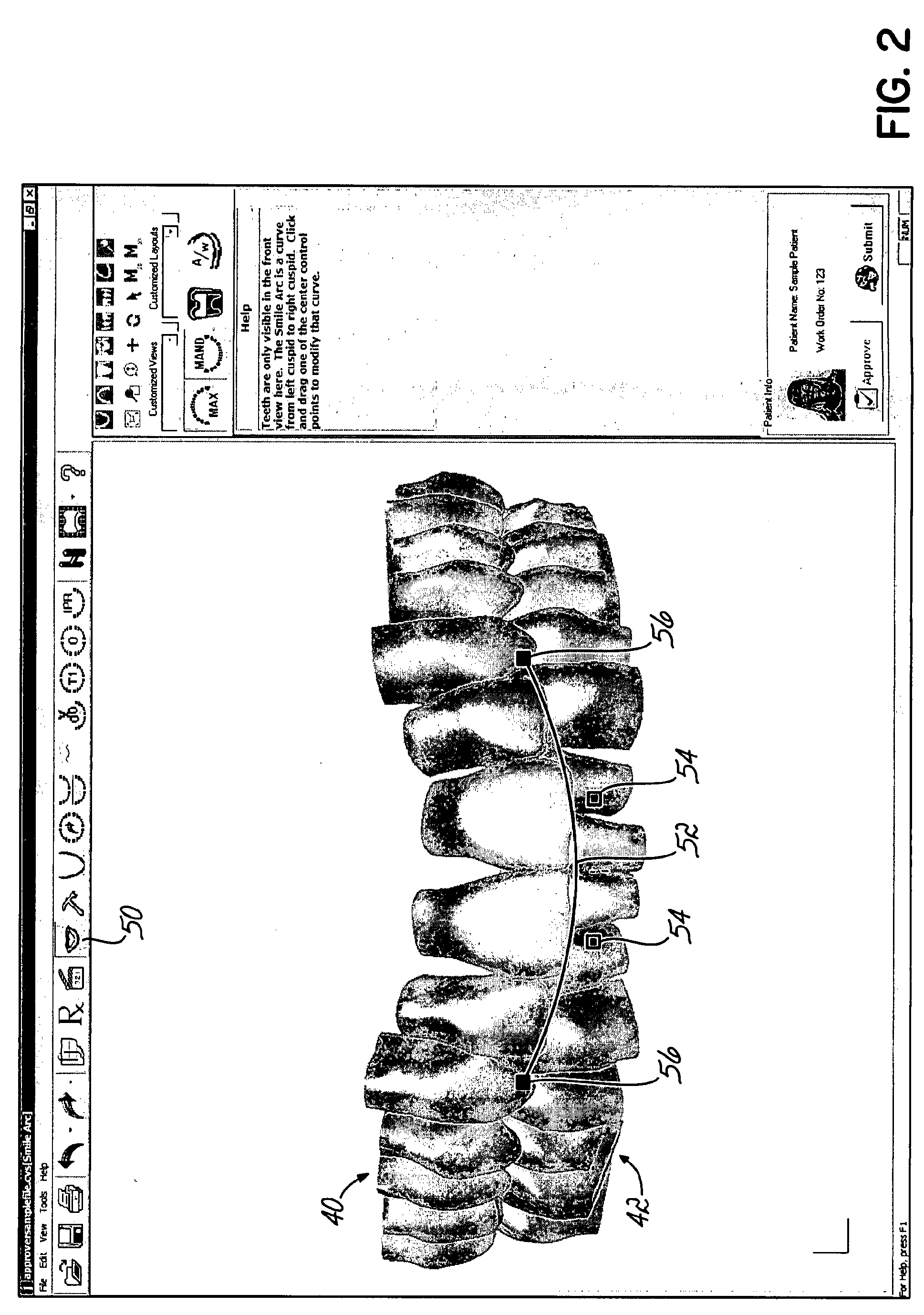
[0064]Traversing the functionality of the software containing the computer implemented method, and referring now to FIGS. 1 through 3, upon picking a Smile Arc icon 50, a user may see both the assemblies (maxillary 40 and mandibular 42) in front view along with a smile arc 52. ...


PUM


Abstract

Computer-implemented methods to plan, display and evaluate orthodontic treatment plans. A plurality of teeth in a representation on a computer display may be moved simultaneously in accordance with a mathematically defined pattern. Software tools available to generate the treatment path may include adjusting the smile teeth, moving teeth along a curve fit to points in the mandible, individually moving a tooth, cross sectioning to check for interference and simulations of occlusal points, highlighting teeth that have moved from their original position, making notations on the teeth, and generating and saving animation sequences of before and after treatment tooth positions.

Description

CROSS REFERENCE TO RELATED APPLICATIONS[0001]This application claims the benefit of the U.S. Provisional Application Ser. No. 60 / 777,483, filed 28 Feb. 2006 and entitled SOFTWARE AND METHODS FOR DENTAL TREATMENT PLANNING.FIELD OF THE INVENTION[0002]The invention relates generally to the field of orthodontics and, more particularly, to computer-automated development of an orthodontic treatment plan and appliance.BACKGROUND OF THE INVENTION[0003]The orthodontic treatment of patients has as its fundamental objective the repositioning or realignment of the teeth of a patient in the patient's mouth to positions where they function optimally together and occupy relative locations and orientations that define a pair of opposed and cooperating planar, or nearly planar, smooth arches. The teeth of the two arches, the maxillary arch of the teeth of the upper jaw and the mandibular arch of the teeth of the lower jaw, when in optimal or ideal positions, contact the teeth of the opposite arch al...

Claims


Application Information

Patent Timeline
Patent Type & Authority Applications(United States)
IPC IPC(8): A61C7/00
CPCG06F19/3406G16H40/63G16H50/50Y02A90/10A61C7/002
Inventor ANDREIKO, CRAIG A.
Owner ORMCO CORP
Why Eureka
Try Eureka