Flow meter

a flow meter and flow rate technology, applied in the direction of fluid pressure measurement, liquid/fluent solid measurement, machine/engine, etc., can solve the problems of inability to exploit the accuracy of modern engine control systems, limited range of flow meter, etc., and achieve high accuracy and precise mass flow computation. , the effect of prolonging the turn-down ratio

Inactive Publication Date: 2009-04-16
ELDEC CORP
View PDF10 Cites 12 Cited by
  • Summary
  • Abstract
  • Description
  • Claims
  • Application Information

AI Technical Summary

Benefits of technology

[0004]The present invention provides a volumetric flow meter in combination with a densitometer to provide a mass flow measurement. The volumetric flow meter relies on an variable area obstruction meter to yield an extended turn-down ratio without active controlling mechanisms and a differential pressure sensor to measure the pressure difference across the obstruction. The densitometer relies on capacitance tubes to yield a density measurement of the fluid passing there through. A fuel temperature sensor serves to correct both the pressure bridge signal as well as the density signal to enable a highly accurate and precise mass flow computation to be performed.

Problems solved by technology

Heretofore used volumetric flow meters have a limited range and are incapable of providing the accuracy that can be exploited by modern engine control systems.

Method used


Image

  • Flow meter
  • Flow meter
  • Flow meter

Examples


Embodiment Construction

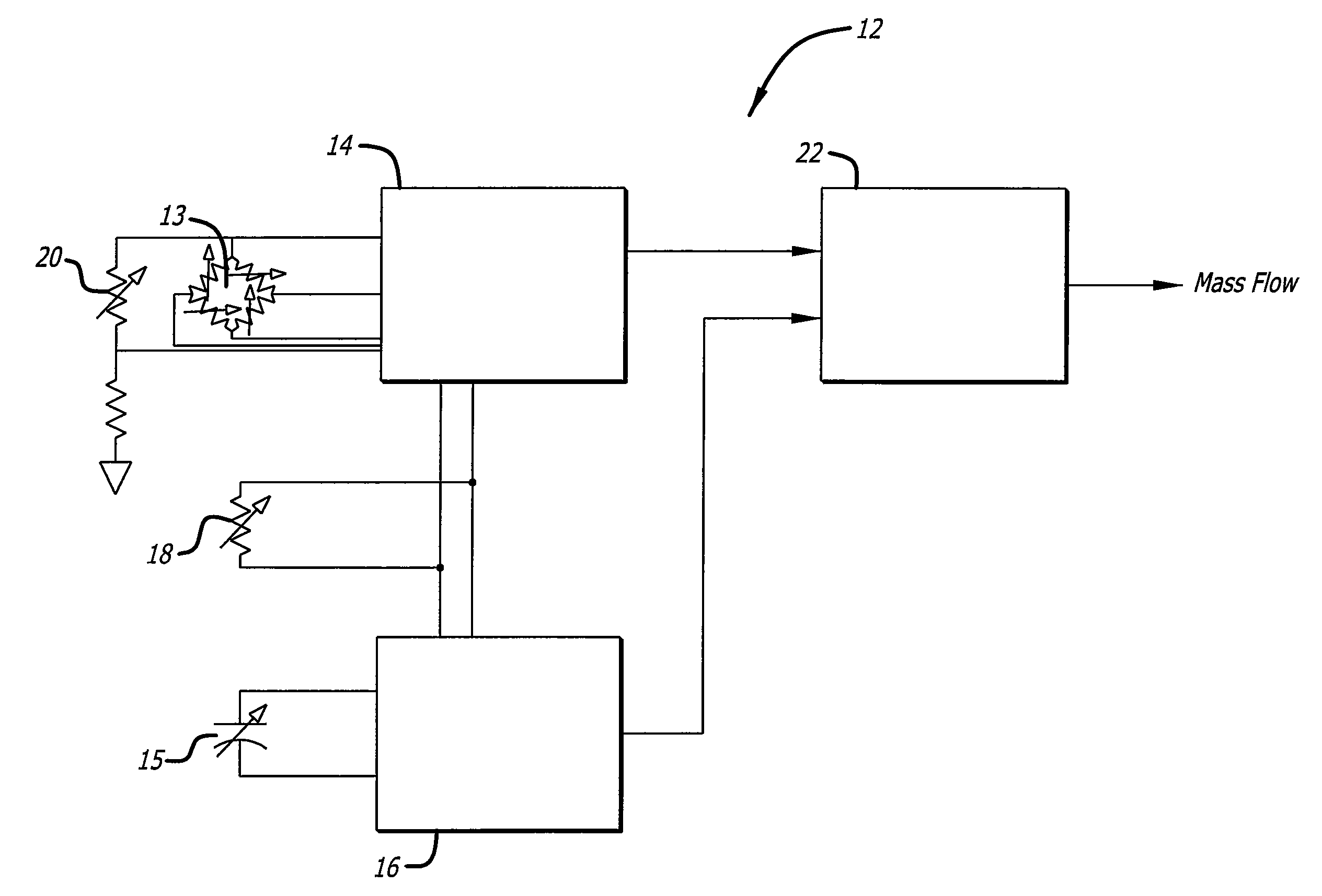
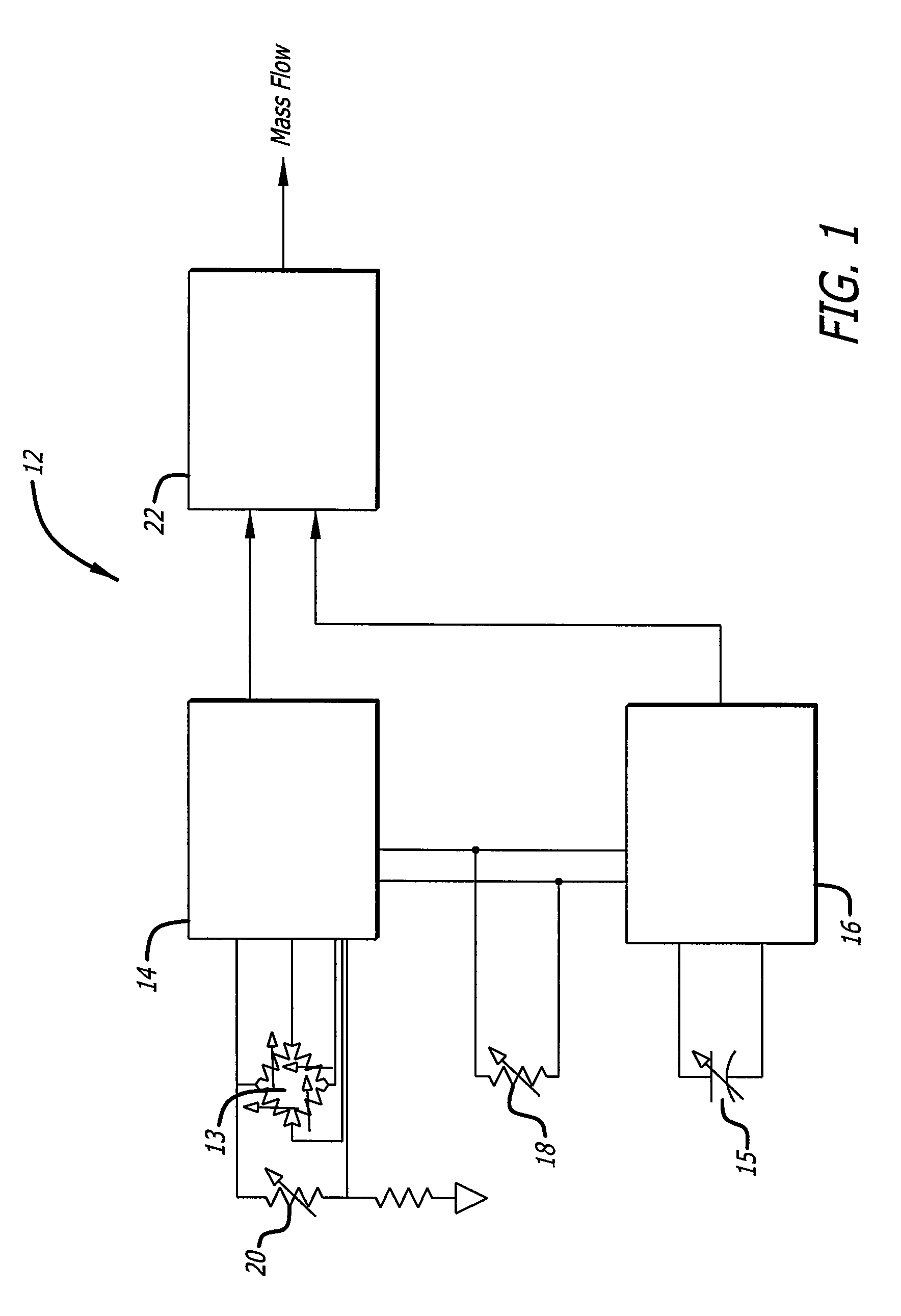
[0011]FIG. 1 is a block diagram providing an overall illustration of the system 12 of the present invention. The pressure differential across an obstruction positioned in the flow path of a liquid is measured via pressure bridge 13 and processed at 14 to yield a pressure signal which is proportional to volumetric flow rate while the capacitance of the flowing liquid is measured at 15 and processed at 16 to yield a density signal. The temperature of the liquid is measured at 18 and is used in the correction of both the pressure bridge signal as well as the densitometer signal. An additional correction 20 of the pressure bridge signal is made as a function of the temperature of the pressure differential sensor itself. The temperature sensor is integrated into the diaphragm of the sensor as the diaphragm temperature may be different than the liquid or environmental temperatures. The final computation of mass flow is made at 22.

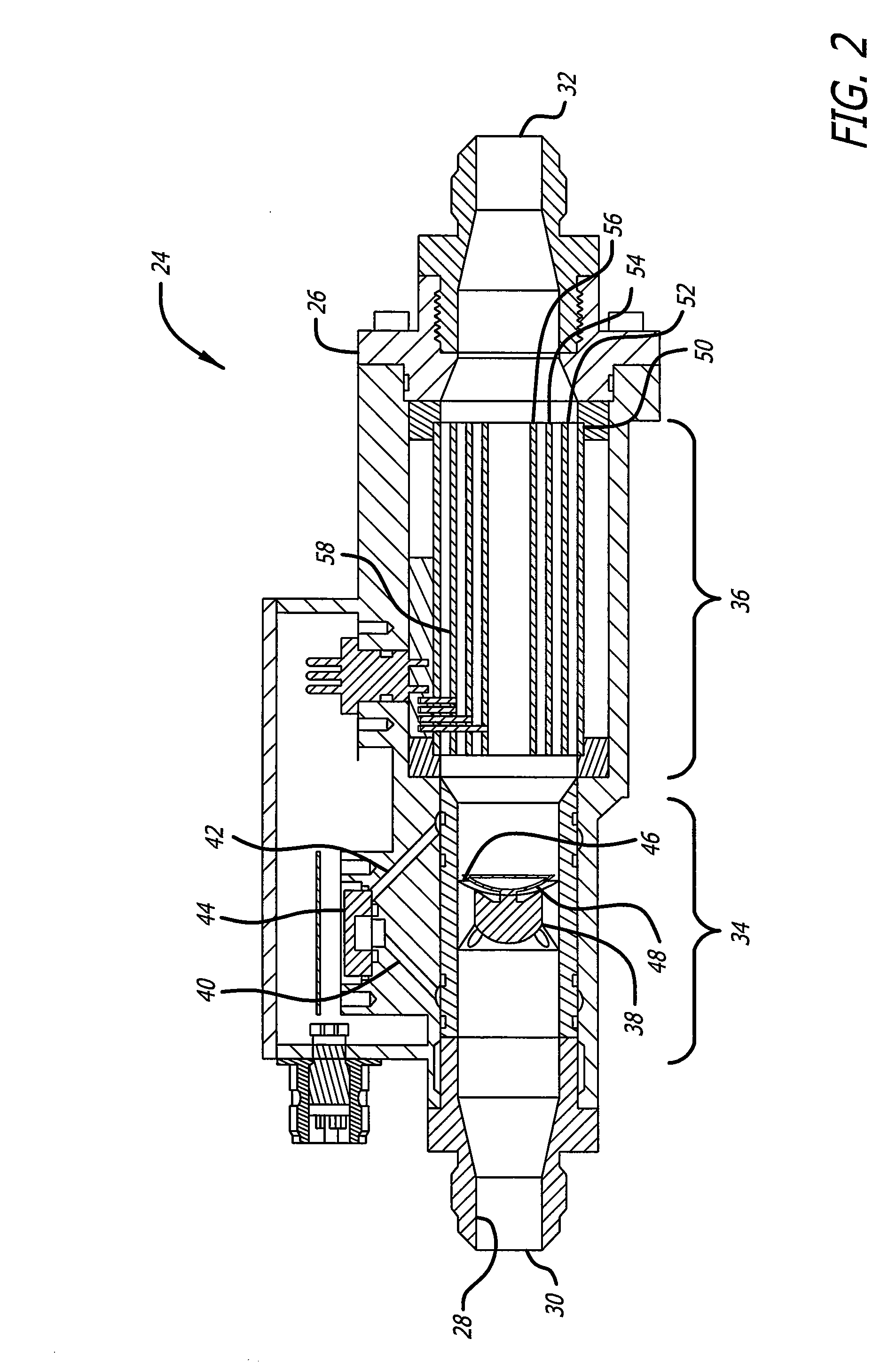
[0012]FIG. 2 is a cross-sectional view of a preferred embod...


PUM


Abstract

A simple, passive and rugged device for measuring the flow rate of liquid. A variable area obstruction valve, a differential pressure sensor and a densitometer are combined in a single housing to provide for a highly accurate and precise measure of mass flow.

Description

CROSS-REFERENCES TO RELATED APPLICATIONS[0001]This application claims priority from U.S. Provisional Application No. 60 / 979,476, filed Oct. 12, 2007, incorporated by reference in its entirety.BACKGROUND[0002]The present invention is generally directed to flow meters and more particularly pertains to a mass flow meter. The device measures both volumetric flow as well as density to yield mass flow.[0003]Aircraft engine and airframe designers seek highly accurate, wide flow range, fast response, and rugged flow meters to measure the flow rate of hydrocarbon based fuel (jet fuel) for the purposes of engine control. Heretofore used volumetric flow meters have a limited range and are incapable of providing the accuracy that can be exploited by modern engine control systems. What is needed is a simple, passive, accurate and reliable method of measuring mass flow.SUMMARY OF THE INVENTION[0004]The present invention provides a volumetric flow meter in combination with a densitometer to provid...

Claims


Application Information

Patent Timeline
Patent Type & Authority Applications(United States)
IPC IPC(8): G01F1/34G01F1/44G01F1/42
CPCG01F15/022G01F1/88
Inventor BOULANGER, MICHAEL P.GREWELL, BRUCE K.
Owner ELDEC CORP
Why Eureka
Try Eureka