Cartridge for a fluid sample analyser

a fluid sample and cartridge technology, applied in the direction of instrumentation, fluid analysis using sonic/ultrasonic/infrasonic waves, material analysis, etc., can solve the problems of limiting the speed of response of the apparatus, inconvenient operation, and high construction complexity of the cartridge, so as to reduce the cost, facilitate manufacturing, and reduce the effect of transport limitations

Active Publication Date: 2009-04-23
ABBOTT RAPID DIAGNOSTICS INT UNLTD
View PDF4 Cites 3 Cited by
  • Summary
  • Abstract
  • Description
  • Claims
  • Application Information

AI Technical Summary

Benefits of technology

[0013]The use of a combination of a membrane and an adhesive between the sensor and support surface enables the flow cell to be formed from relatively simple components, and hence to be relatively cheap. In particular, the support surface can take the form of a simple plate, rather than a support component formed by a dedicated injection moulding process.
[0041]A cartridge in accordance with the invention can provide a low cost, easily manufactured, flow cell of a low volume suitable for minimising transport limitations in the diffusion of analytes to the transducer surface, and which comprises a transducer, the flow cell capable of being mounted and connected simply, robustly and reliably to a measurement instrument.

Problems solved by technology

Such a cartridge is of a relatively complex construction and is therefore relatively expensive, especially since the cartridge is to be used as a disposable unit.
This can prevent the flow cell from achieving rapid immobilisation times, and this correspondingly limits the speed of response of the apparatus.
Additionally the cartridge requires a manual electrical connection operation between the terminal of the transducer and the instrument, which is inconvenient in operation.
It is also known that measurements of kinetic properties of analyte receptor interactions can be limited by the diffusion of analyte to the surface of the transducer.
WO2128372 and WO0247246 propose various means intended to achieve stress free mounting, but in these cases there results a relatively complex multipart design for fabricating a leak tight structure, and further, as with U.S. Pat. No. 6,196,059 above this results in a situation where it is difficult to obtain a low volume of the flow cell.

Method used


Image

  • Cartridge for a fluid sample analyser
  • Cartridge for a fluid sample analyser
  • Cartridge for a fluid sample analyser

Examples


Embodiment Construction

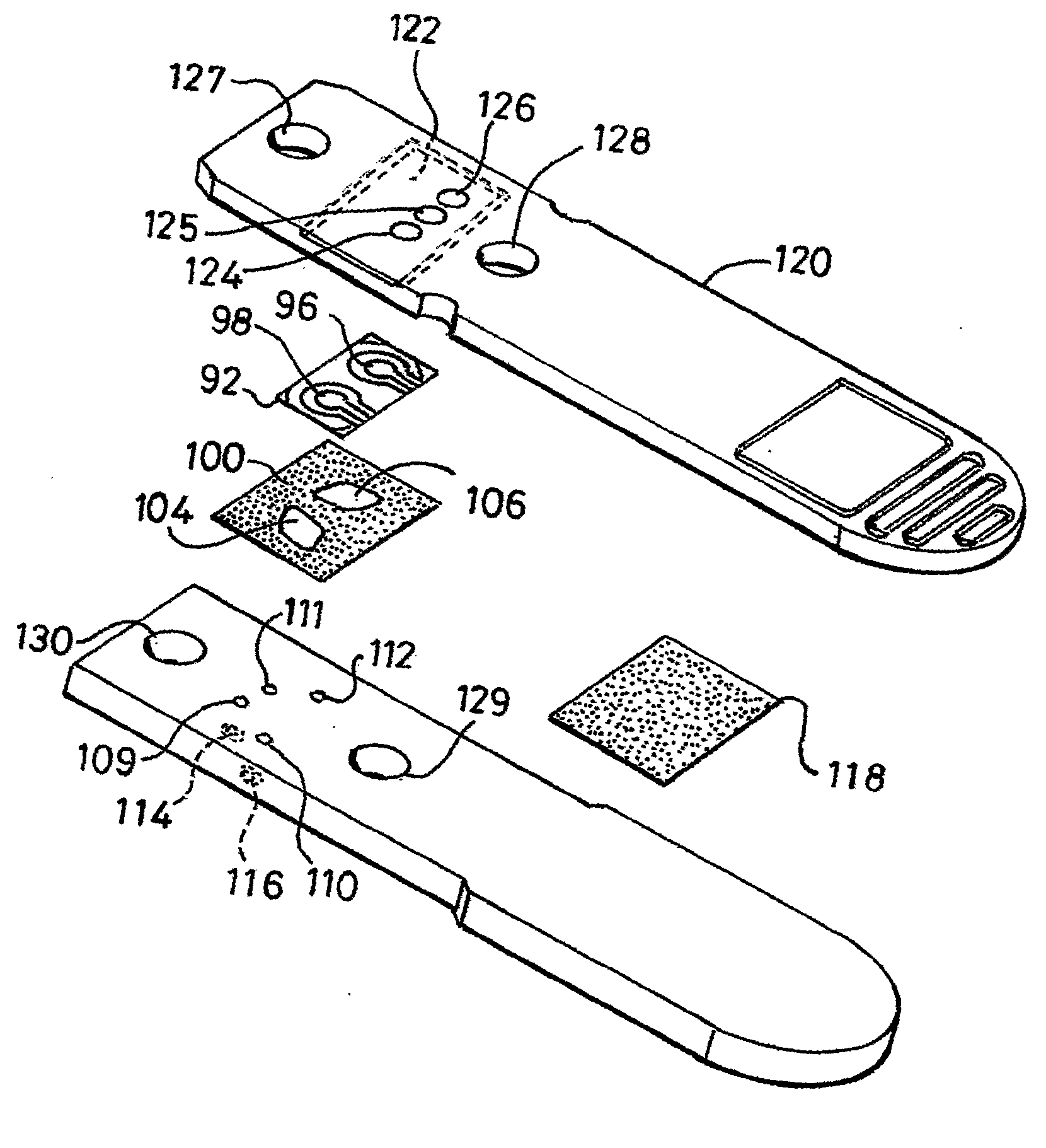
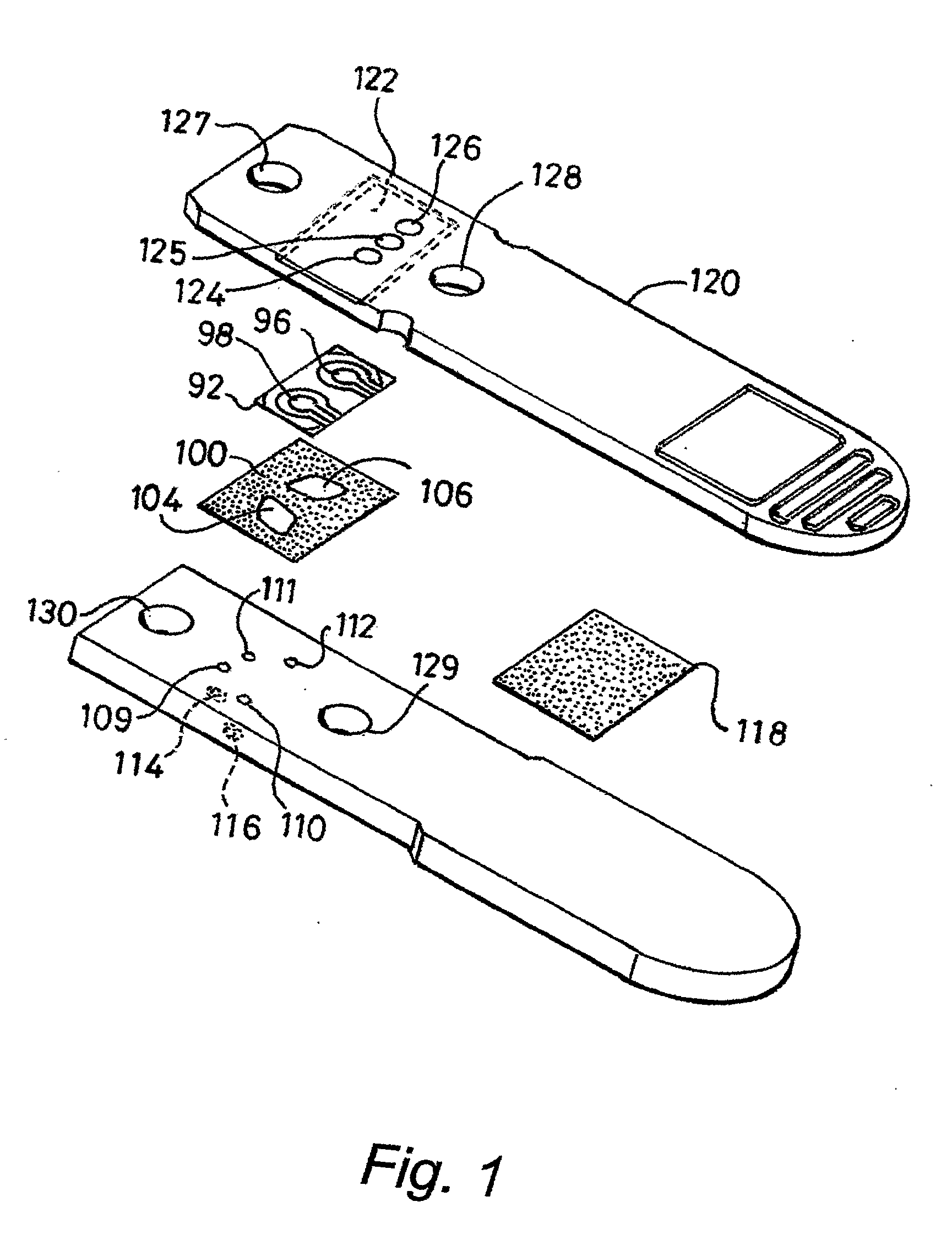
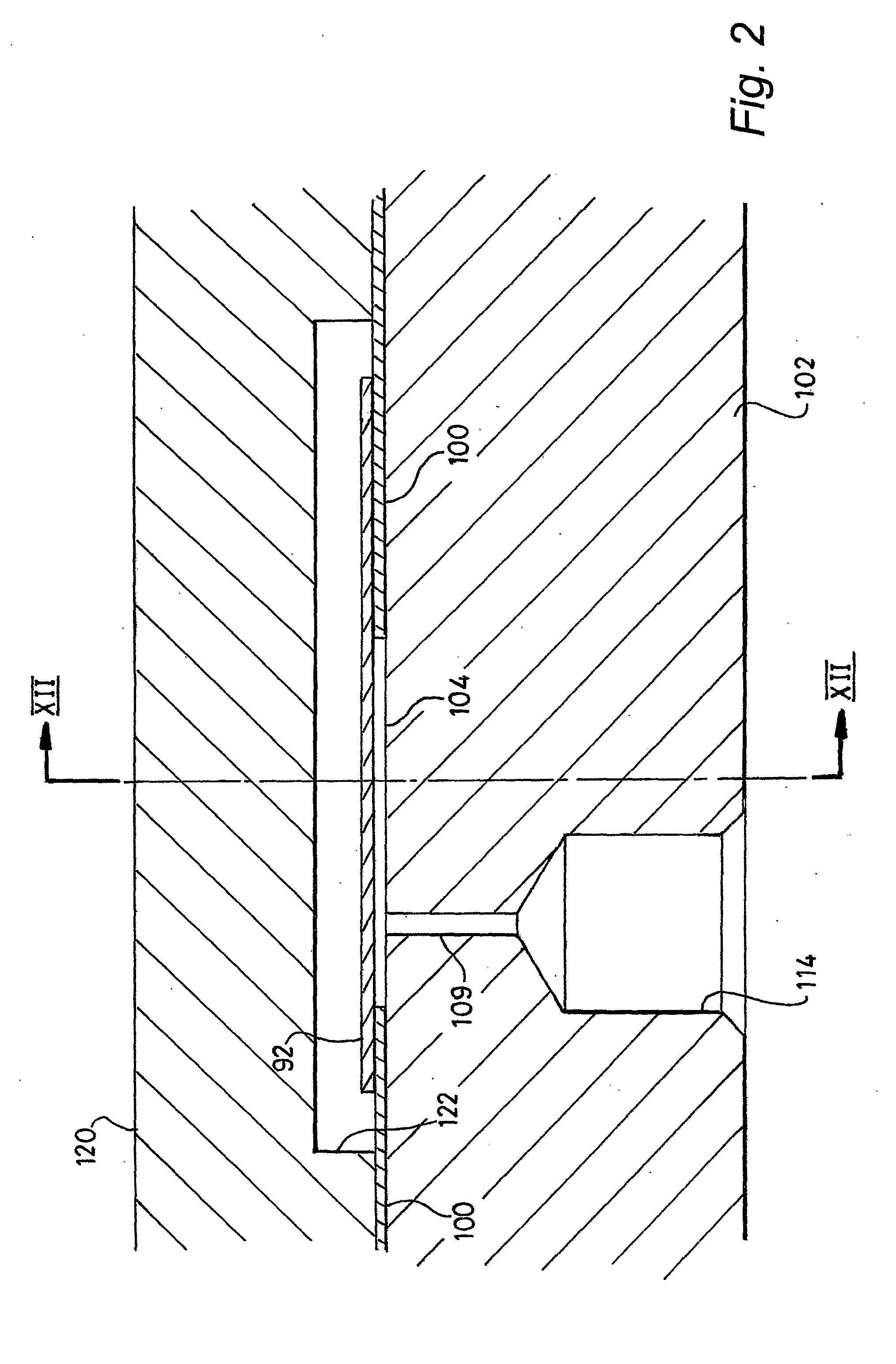
[0051]The cartridge shown in the drawings is for use as part of a quartz crystal microbalance apparatus, which includes a docking station for connecting each of two flow cells in the cartridge to a fluid delivery / removal system and for connecting a transducer in the form of a quartz crystal plate 92 to electrical circuitry for vibrating the crystal and measuring the crystal's vibrational characteristics. Such apparatus is described in the present applicant's co-pending UK patent application number 0506711.1

[0052]As is indicated above, the quartz crystal plate 92 forms part of the cartridge shown in the drawings. The plate is coated on one surface with gold in a pattern that defines a pair of drive electrodes 96 and 98, each of which is in registry with a respective one of two separate flow cells. The underside of the plate is also coated with gold to form a common earth electrode. A conductive track (not shown) runs from this electrode around the edge of the plate to the top surface...


PUM

PropertyMeasurementUnit
thicknessaaaaaaaaaa
thicknessaaaaaaaaaa
thicknessaaaaaaaaaa

Abstract

A cartridge for apparatus for analysing a sample comprising a fluid as a flow cell for receiving the sample. The cell is formed from a substantially rigid support surface (102), a sensor comprising an electrical mechanical transducer (92), for example a wafer of quartz crystal and adhesive means, such as double sided adhesive tape (100) attaching the sensor to the support surface. The support surface and sensor are spaced from each other by a membrane, which may form part of the double sides adhesive tape so as to define the flow cell between the support surface and the sensor. The flow cell also has an opening (for example, 111) through which, in use, the sample passes. The sensor, forming part of the flow cell, comes into contact with the sample to enable the sample to be analysed.

Description

[0001]This invention relates to a cartridge for apparatus for analysing a sample comprising a fluid, and in particular to a cartridge having a sensor, for performing that analysis, comprising an electrical-mechanical transducer.BACKGROUND TO THE INVENTION[0002]The invention is applicable to apparatus in which a transducer modifies an applied electrical signal, in particular piezoelectric transducers, for example a quartz crystal microbalance system, where the transducer vibrates at a frequency at or close to its resonant frequency.[0003]The transducer typically has an active surface on which a receptor group is immobilised. That group has a chemical affinity or reactivity towards the substance to be detected or analysed. The substance to be analysed is normally present in a fluid which is brought into contact with the active surface of crystal.[0004]Physical, chemical and biochemical interactions between the receptor group on the surface and the substance cause a change in the mass ...

Claims


Application Information

Patent Timeline
Patent Type & Authority Applications(United States)
IPC IPC(8): G01H17/00G01N27/00G01N29/02G01N29/22
CPCG01N29/022G01N29/222G01N2291/0426G01N2291/0422G01N2291/0256
Inventor GODFREY, DANIEL PETERSONFROGLEY, MARK JOHN
Owner ABBOTT RAPID DIAGNOSTICS INT UNLTD
Why Eureka
Try Eureka