Gear transmission with reduced transmission wall housing deflection

Active Publication Date: 2009-04-23
VOLVO LASTVAGNAR AB
View PDF7 Cites 5 Cited by
  • Summary
  • Abstract
  • Description
  • Claims
  • Application Information

AI Technical Summary

Benefits of technology

[0011]In an additional preferred embodiment, rods are located radially close to the intersections, when seen in axial direction, of the diametrically largest rotating parts of the shafts. Thereby, the rods will be close to the parts of the housing walls that would have the largest deflections if there were no rods. That will give a large reduction of the deflections.
[0012]In another preferred embodiment of the invention, the rods are screws that have a head in one end and threads in the other end. That will facilitate the assembly, especially if the rods are to be preloaded. Furthermore, if one of the housing walls to be connected by the rods is designed to have lubricating liquid on one side only, the threaded end of the screws can be mounted in a tapered boss in that wall. Thereby, possible risks for lubricating liquid leakage can be eliminated.
[0013]In still a

Problems solved by technology

When torque is transferred from one gearwheel to another, significant gear mesh forces arise.
Thereby, in operation the walls of the transmission housings will be subjected to forces that will tend to deflect the walls.
Furthermore, cost-efficient casting methods for light alloys do not permit as large wall thickness as is common in cast iron housings.
Finally, the significantly larger thermal expansion of light alloys compared to steel will cause incre

Method used


Image

  • Gear transmission with reduced transmission wall housing deflection
  • Gear transmission with reduced transmission wall housing deflection
  • Gear transmission with reduced transmission wall housing deflection

Examples


Embodiment Construction

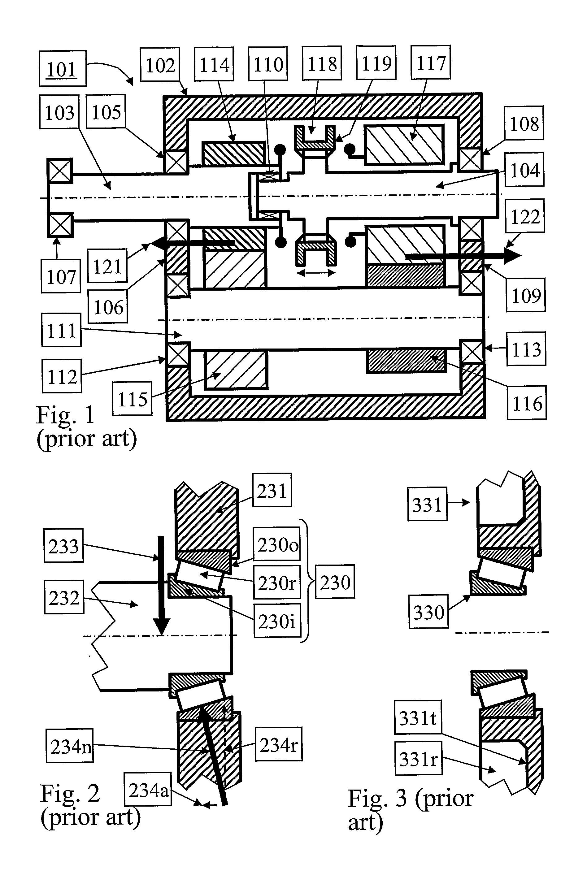
[0024]FIG. 1 shows a simplified longitudinal section of a fix-axes gear transmission 101 with a transmission housing 102, input shaft 103 and output shaft 104. The transmission housing 102 is here shown as a one-piece unit, but it could also have been composed of two or more housing parts. The input shaft 103 is supported by an input shaft bearing 105, which is seated in a front wall 106 of the transmission housing 102, and by a flywheel pilot bearing 107, which is seated in a prime mover output shaft (not shown). Similarly, the output shaft 104 is supported by an output shaft bearing 108 that is seated in a rear wall 109 of the transmission housing 102. The input shaft 103 is substantially coaxial with the output shaft 104. A second point of support for the output shaft 104 is a pilot bearing 110 that is carried by the input shaft 103. Furthermore, there is a countershaft 111 located radially apart from the input shaft 103 and the output shaft 104. The countershaft 111 is supported...


PUM


Abstract

A gear transmission is provided including at least a first and a second shaft with substantially fixed and substantially parallel axes of rotation, a transmission housing with a first and a second wall that extends perpendicular to the axes of rotation, and a plurality of gearwheels that are rotationally fixed or rotationally fixable to the shafts. The shafts include at least one input shaft and at least one output shaft, the shafts being suspended by bearings that are seated in the first and second walls. The first wall is connected to the second wall with at least one rod in order to reduce deflections in operation of the first and second walls.

Description

BACKGROUND AND SUMMARY[0001]The present invention relates to gear transmissions, and more particularly to a system for decreased deflection of transmission housing walls that are subjected to bearing loads.[0002]Fix-axes gear transmissions are used in many fields of technology, for instance in vehicles in manually shifted or automated form. They comprise a number of gearwheels that are located on a number of shafts. The shafts are supported by bearings that are seated in a transmission housing. The rotational axes of the shafts are thereby substantially fixed, hence the designation fix-axes gear transmissions. When torque is transferred from one gearwheel to another, significant gear mesh forces arise. These gear mesh forces will create reaction forces in the bearings. Thereby, in operation the walls of the transmission housings will be subjected to forces that will tend to deflect the walls. For proper function and life of the gearwheels and bearings, it is important that these def...

Claims


Application Information

Patent Timeline
IPC IPC(8): F16H57/02F16H57/022F16H57/03
CPCF16H57/022Y10T74/2186F16H2057/0206F16H57/03
Inventor HEDMANZETTERGREN, LARS
Owner VOLVO LASTVAGNAR AB
Why Eureka
Try Eureka