Eureka AIR delivers breakthrough ideas for toughest innovation challenges, trusted by R&D personnel around the world.

Regulating Transmission Fluid and Engine Coolant Temperatures in a Motor Vehicle

Inactive Publication Date: 2009-04-23
FORD GLOBAL TECH LLC
View PDF11 Cites 51 Cited by
  • Summary
  • Abstract
  • Description
  • Claims
  • Application Information

AI Technical Summary

Benefits of technology

[0009]The engine coolant side bypass valve bypasses the ATF heat exchanger whenever the heat core discharge temperature is below a desired threshold. Then the first heat exchanger can be nearly any size without compromising the rate at which temperature of the heater core increases below that threshold. Above that temperature threshold, the bypass valve will open, thereby admitting coolant into the first heat exchanger.
[0010]ATF always flows through the heat exchanger. The second bypass valve senses the return oil temperature and, that temperature is below a reference temperature, e.g. 200° F., it will return to the transmission, which is a bypass to any auxiliary cooler in the ATF cooling loop. If the oil temperature is greater than the reference temperature, the ATF bypass valve opens, thereby admitting oil to flow to the auxiliary cooler, then return to the transmission.
[0011]The system provides additional packaging advantages when including both the water-side bypass, ATF-bypass and first heat exchanger as one assembly.

Problems solved by technology

But cooler bypass valves have limited effect on warm up rates after a cold start.
Although the oil-to-water cooler located in the engine coolant loop provides a solution for light duty vehicles, it is not capable of cooling heavier duty applications, such heavy duty trucks and other towing vehicles, due to their high coolant temperatures and a need for the transmission to run at temperatures close to the maximum engine coolant temperature.
Furthermore, performance of the passenger compartment heater is compromised when engine coolant is used to heat the transmission.
Warming the transmission causes a lower coolant temperature, which reduces heater performance and slows delivery of heat to the passenger compartment.

Method used


Image

  • Regulating Transmission Fluid and Engine Coolant Temperatures in a Motor Vehicle
  • Regulating Transmission Fluid and Engine Coolant Temperatures in a Motor Vehicle

Examples


Embodiment Construction

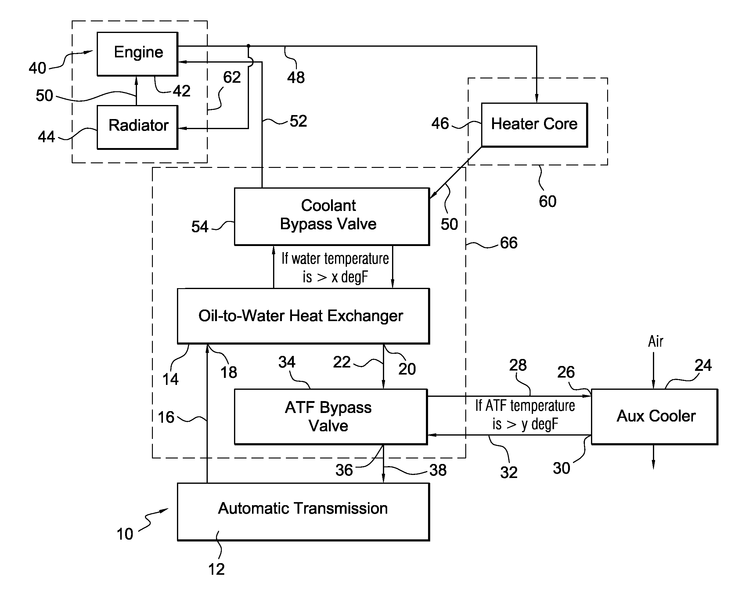
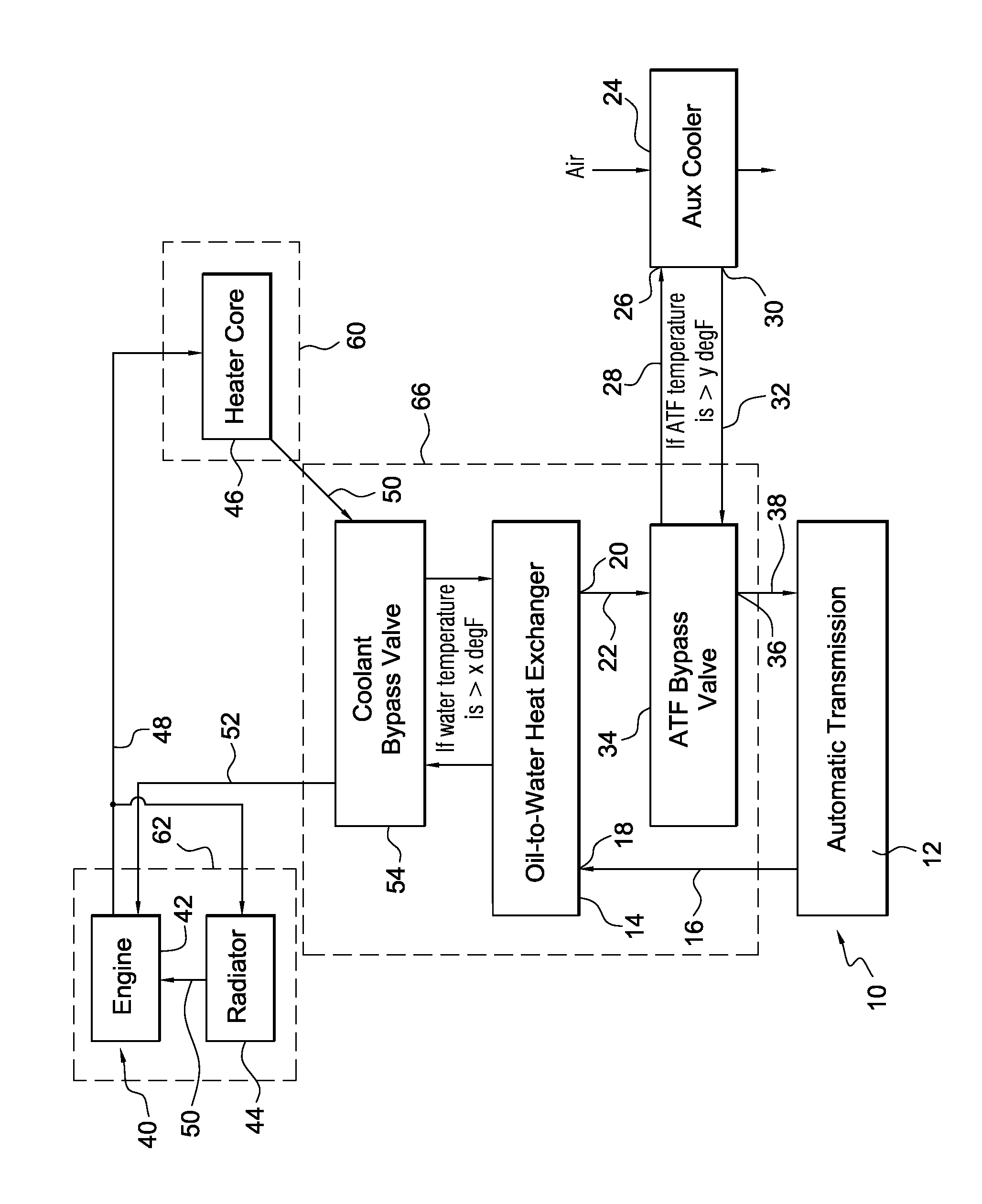
[0015]A automatic transmission 10 includes a oil sump 12, which is a source of transmission fluid, from which transmission fluid is supplied to the intake side of a transmission pump (not shown) and into which fluid is delivered from the hydraulic circuit of the transmission after the fluid lubricates and carries heat from the clutches, bearings, shafts, gears and other components of the transmission.

[0016]A first heat exchanger 14, which communicates with the source of transmission fluid 12 through an oil line 16, is adapted to carry engine coolant and to transfer heat between the engine coolant and the transmission fluid. Heat exchanger 14 includes a first inlet 18 through which transmission fluid enters heat exchanger 14 from line 16, and a first outlet 20 through which transmission fluid exits the heat exchanger and enters a line 22.

[0017]A second heat exchanger 24 includes a passageway through which ambient air may flow, transfers heat between the transmission fluid and the air...


PUM


Abstract

A system for controlling the temperature of a transmission fluid includes a first heat exchanger communicating with a source of engine coolant for transferring heat between the engine coolant and the transmission fluid and including a first outlet through which transmission fluid exits the first heat exchanger, a second heat exchanger through which air may flow for transferring heat between the transmission fluid and the air and including a second inlet through which transmission fluid enters the second heat exchanger, and second outlet through which transmission fluid exits the second heat exchanger, and a first bypass valve for alternately opening and closing the second inlet and the second outlet when a temperature of transmission fluid exiting the first outlet is greater than a first reference temperature, and for bypassing the second heat exchanger when the temperature of transmission fluid exiting the first outlet is less than the second reference temperature.

Description

BACKGROUND OF THE INVENTION[0001]1. Field of the Invention[0002]This invention relates generally to apparatus for regulating the temperature of transmission fluid and engine coolant in a motor vehicle.[0003]2. Description of the Prior Art[0004]A transmission cooling system may include an oil-to-water cooler or an oil-to-air cooler, or both of these, which remove heat contained in the transmission oil and are sized to accommodate a heat load produced when the transmission is operating under severe duty conditions. To reduce transmission friction, it is desirable to run the transmission at a relatively high temperature. The higher temperature reduces oil viscosity, which is one of the larger contributors to internal friction.[0005]A cooler bypass valve may be used to reduce heat transfer from the transmission oil when cooling is not desired, so that internal friction can warm the transmission oil to the desired operating temperature. But cooler bypass valves have limited effect on war...

Claims


Application Information

Patent Timeline
IPC IPC(8): F28D15/00F16H57/04
CPCF01P7/165F01P2060/045F16H57/0417F16H57/0413F01P2060/08F01P3/20F01P11/08F16H57/0412
Inventor GOODEN, JAMES T.BISHOP, BRIAN D.GARDNER, GREGORY D.
Owner FORD GLOBAL TECH LLC
Why Eureka
Eureka Blog
Learn More