Internal combustion engine cooling system

a technology for internal combustion engines and cooling systems, which is applied in the direction of engine cooling apparatus, machines/engines, measurement devices, etc., can solve the problems of reducing the heat dissipation of the coolant, and abnormal cooling of the radiator, so as to prevent the overheating of the internal combustion engine, reduce the fuel consumption, and reduce the fuel consumption

Inactive Publication Date: 2007-02-27
DENSO CORP
View PDF7 Cites 11 Cited by
  • Summary
  • Abstract
  • Description
  • Claims
  • Application Information

AI Technical Summary

Benefits of technology

[0006]Accordingly, it is a first object of the present invention to provide an internal combustion engine cooling system capable of keeping an internal combustion engine at its most efficient temperature by properly regulating the temperature of the cooling water for cooling the internal combustion engine according to various conditions, and of reducing fuel consumption.
[0007]It is a second object of the present invention to provide an internal combustion engine cooling system capable of preventing an internal combustion engine from overheating due to the malfunction of a flow control valve placed in a coolant bypass passage.
[0008]An internal combustion engine cooling system according to the first aspect of the present invention mixes the coolant flowing from an internal combustion engine and cooled while flowing through a radiator, and the coolant from a bypass passage bypassing the radiator in a flow control valve, circulates the coolant by a water pump placed in an inlet or an outlet passage, and controls the temperature of the coolant flowing through the outlet passage on the basis of a desired coolant temperature set for the coolant flowing through the outlet passage. The desired coolant temperature is adjusted according to the operating condition of the internal combustion engine, the traveling mode of the vehicle with the internal combustion engine and environmental conditions. Thus, the desired coolant temperature can properly be adjusted in a narrow temperature range near a detonation limit temperature, detonation can be prevented with a sufficient allowance, the internal combustion engine is kept at its most efficient temperature and fuel consumption can be reduced.
[0009]An internal combustion engine cooling system according to the second aspect of the present invention monitors a flow control valve, and performs a heat generation rate reducing control operation for reducing the heat generation of an internal combustion engine when the flow control valve malfunctions. Thus, even if the coolant of an excessively high temperature should be supplied to the internal combustion engine and the cooling capacity of the coolant should be reduced due to malfunction of the flow control valve, the increase of the temperature of the internal combustion engine can be suppressed and the internal combustion engine can be prevented from overheating.

Problems solved by technology

However, the coolant of an elevated temperature tends to cause detonation If the flow control valve fails to operate normally due to obstruction by foreign matters stuck in the flow control valve or the malfunction of a drive circuit, it is possible that the flow of the coolant through the radiator decreases abnormally, the dissipation of the heat of the coolant by the radiator decreases, the temperature of the coolant flowing into the internal combustion engine increases abnormally, the cooling capacity of the coolant decreases and the internal combustion engine overheats.
However, since the coolant temperature is decreased by the fixed temperature, the coolant cannot be adjusted to an optimum temperature, and the fixed temperature can be insufficient or excessive depending on the variation of parameters such as those indicating the operating condition of the internal combustion engine and the quality of the fuel.
Since this coolant temperature control increases or decreases the coolant temperature gradually, the coolant temperature control is not necessarily able to deal properly with operating conditions, traveling modes or environmental conditions, and causes detonation in a coolant temperature range near a detonation limit temperature above which detonation occurs.

Method used


Image

  • Internal combustion engine cooling system
  • Internal combustion engine cooling system
  • Internal combustion engine cooling system

Examples


first embodiment

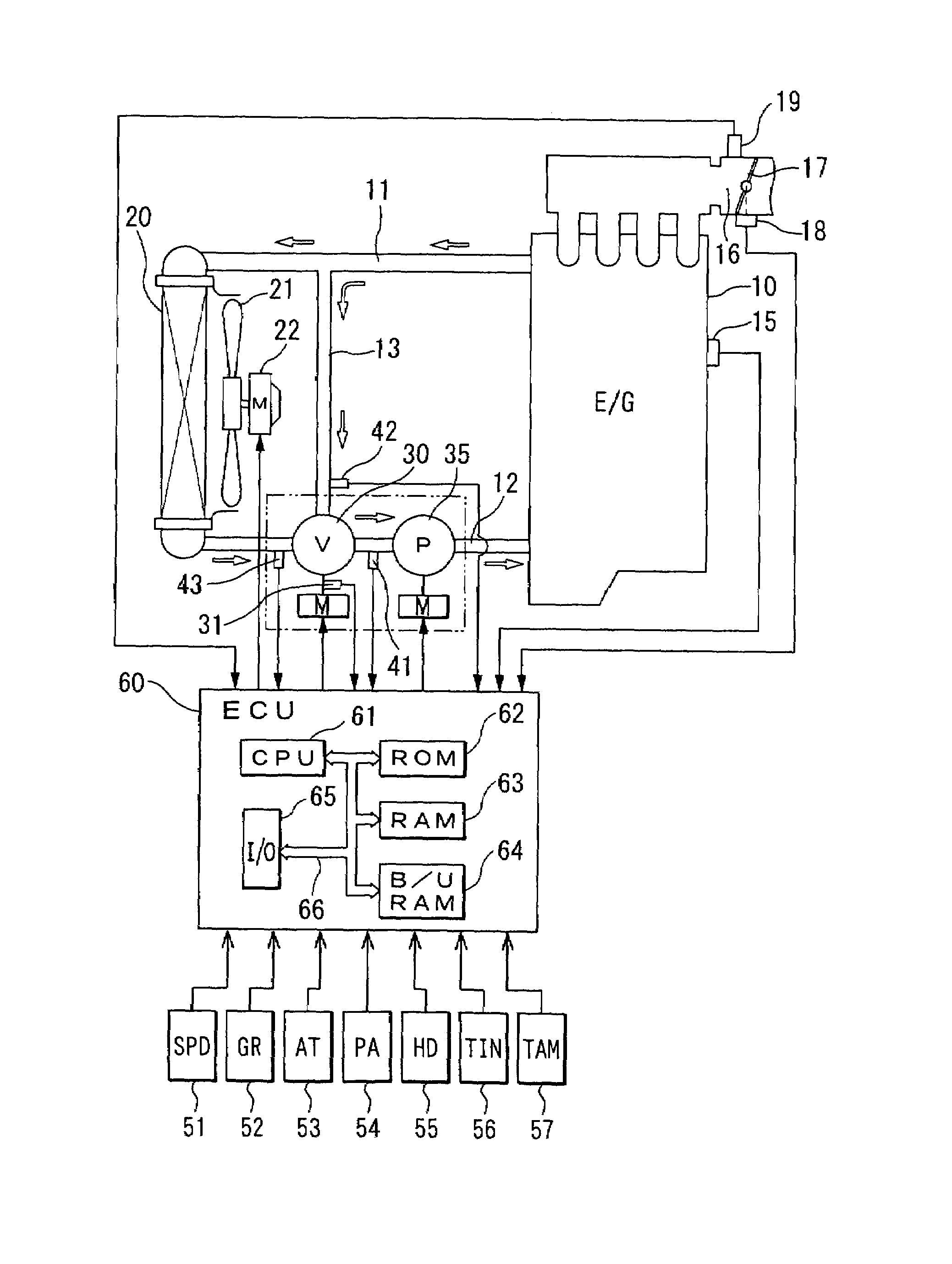
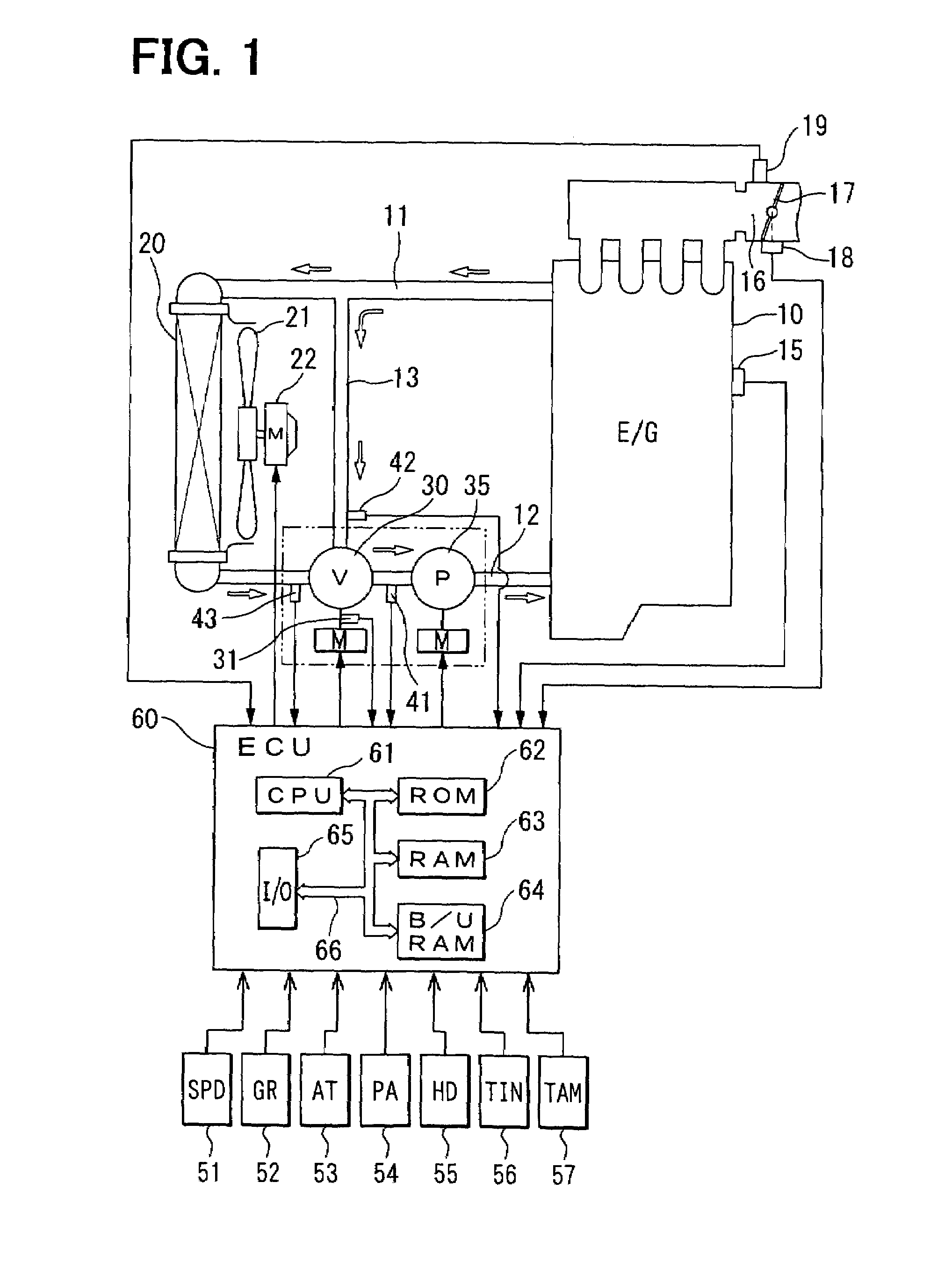
[0035]Referring to FIG. 1, an internal combustion engine 10 is connected to a radiator 20 for cooling engine cooling water (coolant) following through an inlet passage 11 and an outlet passage 12. The inlet passage 11 and the outlet passage 12 are connected by a bypass passage 13. A rotary flow control valve 30 is placed at the junction of the outlet passage 12 and the bypass passage 13. An electric water pump 35 is placed between the flow control valve 30 and the engine 10 in the outlet passage 12. A radiator fan 21 is disposed behind the radiator 20. A fan motor 22 drives the radiator fan 21 when necessary.

[0036]A potentiometer 31 is combined with the valve shaft, not shown, of the flow control valve 30 to measure the valve opening of the flow control valve 30. A first coolant temperature sensor 41 for measuring the temperature of the coolant flowing into the electric water pump 35, i.e., inlet coolant temperature is placed between the flow control valve 30 and the electric motor ...

second embodiment

[0046]A traveling mode determining routine shown in FIG. 3 and a coolant temperature control routine shown in FIG. 4 carried out in the second embodiment will be described. The CPU 61 repeats the traveling mode determining routine and the coolant temperature control routine at a predetermined period.

[0047]Referring to FIG. 3, the ECU 60 receives the engine speed signal NE, i.e., a signal indicating the operating condition of the engine 10, provided by the engine speed sensor 15, the intake pressure signal PM, i.e., a signal indicating load on the engine 10, provided by the intake pressure sensor 19, and the vehicle speed signal SPD provided by the vehicle speed sensor 51 or the AT control signal AT provided by an AT controller 53 at step 201. At step 202, a traveling mode, i.e., an uphill traveling mode, a downhill traveling mode or a level traveling mode, is determined from maps stored in the ROM 62 by using the engine speed signal, the intake pressure signal and the gear ratio sig...

third embodiment

[0054]A steady / transient traveling state determining routine shown in FIG. 5 and a coolant temperature control routine shown in FIG. 6 carried out by the ECU 60 in the third embodiment will be described. The CPU 61 repeats the steady / transient traveling state determining routine and the coolant temperature control routine at a predetermined period.

[0055]Referring to FIG. 5, the ECU 60 receives the engine speed signal NE, i.e., a signal indicating the operating condition of the engine 10, provided by the engine speed sensor 15, the intake pressure signal PM, i.e., a signal indicating load on the engine 10, provided by the intake pressure sensor 19, and the vehicle speed signal SPD provided by the vehicle speed sensor 51 or the AT control signal AT provided by the AT controller 53 at step 301. Then, at step 302, an integrated change of loads (intake pressure, throttle opening and amount of intake air) on the engine 10 or an integrated change of engine speed is calculated for steady / tr...


PUM


Abstract

In a cooling system of an internal combustion engine, coolant flowing through a radiator and bypassing the radiator are mixed in a flow control valve controlled by ECU on the basis of signals provided by sensors such as a coolant temperature sensor, so that the coolant is circulated by an electric pump to control the coolant temperature for the internal combustion engine. A desired coolant temperature is changed according to the operating condition of the internal combustion engine, the traveling condition of a vehicle and the ambient condition. Thus, the temperature of the coolant flowing into the internal combustion engine is changed properly so that frictional resistance in the engine and exhaust gas may be reduced and the internal combustion engine may be kept at its most efficient temperature near a detonation limit temperature.

Description

CROSS REFERENCE TO RELATED APPLICATION[0001]This application is related to and incorporates herein by reference Japanese Patent Applications No. 2002-289435 filed on Oct. 2, 2002 and No. 2002-321514 filed on Nov. 5, 2002.FIELD OF THE INVENTION[0002]The present invention relates to an internal combustion engine cooling system for properly controlling the temperature of cooling water (coolant) for cooling an internal combustion engine so that the internal combustion engine is kept at its most efficient temperature.BACKGROUND OF THE INVENTION[0003]Internal combustion engine cooling systems are disclosed in U.S. Pat. No. 6,390,031 B1 (JP-A-2000-45773) and Japanese Laid-open Publication No. 5-288054.[0004]The internal combustion engine cooling system disclosed in the U.S. Patent has a bypass passage bypassing a radiator and provided with a flow control valve, and keeps the coolant for cooling an internal combustion engine at an elevated temperature to reduce frictional resistance and fue...

Claims


Application Information

Patent Timeline
Patent Type & Authority Patents(United States)
IPC IPC(8): F01P7/14F01P7/16
CPCF01P7/164F01P7/167F01P2025/60F01P2025/36F01P2007/146
Inventor NAKANO, KAZUMI
Owner DENSO CORP
Why Eureka
Try Eureka