Coil unit of induction heating fixing device

a technology of induction heating and fixing device, which is applied in the direction of electric/magnetic/electromagnetic heating, electrographic process, instruments, etc., can solve the problems of vibration in the coil, change in the heat generation characteristic of the metal conductive layer, and impaired fixing performance, so as to simplify the coil unit and achieve high induction heating performance

Inactive Publication Date: 2009-04-23
KK TOSHIBA +1
View PDF6 Cites 15 Cited by
  • Summary
  • Abstract
  • Description
  • Claims
  • Application Information

AI Technical Summary

Benefits of technology

[0010]An aspect of the invention is to provide a coil unit of an induction heating fixing device in which a wire of a coil to be extended to the outside of the coil unit is eliminated to simplify the coil unit, and induction heating performance is high.

Problems solved by technology

On the other hand, at the time of power supply to the coil, vibration occurs in the coil by high frequency current flowing through the coil.
By this, there is a fear that the heat generation characteristic of the metal conductive layer is changed, and the fixing performance is impaired.
Thus, there is a fear that noise due to magnetic field by the wire in the periphery of the coil unit is generated.
Thus, in the case where the heat roller is heated by plural coil units, the space for the wire of a joint portion of adjacent coil units becomes wide, and there is also a fear that the uneven temperature of the heat roller occurs.
In particular, in the case where such as the wire is composed of a litz wire made of plural copper wires, when the diameter of the wire becomes large, the space for extending the wire also becomes large.

Method used


Image

  • Coil unit of induction heating fixing device
  • Coil unit of induction heating fixing device
  • Coil unit of induction heating fixing device

Examples


Embodiment Construction

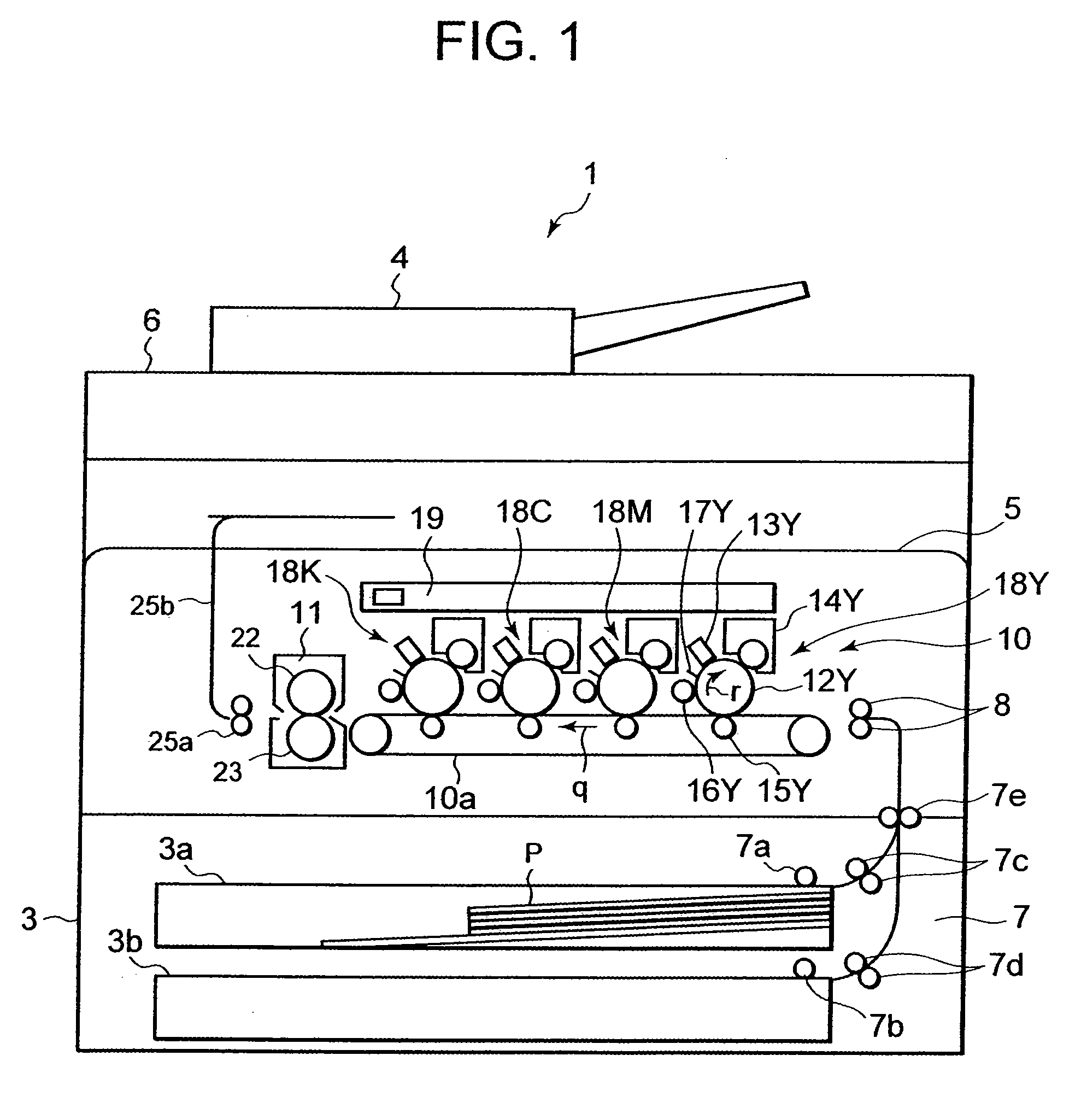
[0019]Hereinafter, an embodiment of the invention will be described in detail with reference to the accompanying drawings. FIG. 1 is a schematic structural view showing a four-tandem color copier 1 in which a fixing device 11 as an induction heating fixing device of the embodiment of the invention is mounted. The color copier 1 includes a scanner unit 6 which is disposed on an upper side and is for reading an original document fed by an automatic document feeder 4. The color copier 1 includes an image forming unit 10 having four sets of image forming stations 18Y, 18M, 18C and 18K of yellow (Y), magenta (M), cyan (C) and black (K) arranged in parallel along a transfer belt 10a.

[0020]The image forming station 18Y of yellow (Y) includes a charger 13Y, a developing device 14Y, a transfer roller 15Y, a cleaner 16Y, and a charge removal unit 17Y, which are process members and are arranged around a photoconductive drum 12Y as an image carrier to be rotated in an arrow r direction. A lase...


PUM


Abstract

In an embodiment of the invention, a plug is connected to an end of a litz wire of an electromagnetic induction coil. In a state where the plug is protruded, the electromagnetic induction coil, an insulating plate, a magnetic core and a coil holder are integrally sealed with a coil mold. A center coil unit, a first and a second side coil units are arranged to be opposite to a heat roller, the plug is inserted in a socket of a power source code or a connection code, and the electromagnetic induction coil can be connected to a power source.

Description

CROSS-REFERENCE TO RELATED APPLICATION[0001]This application is based upon and claims the benefit of priority from U.S. Provisional Application Ser. No. 60 / 981,789 filed on Oct. 22, 2007, the entire contents of which are incorporated herein by reference.BACKGROUND OF THE INVENTION[0002]1. Field of the Invention[0003]The present invention relates to a coil unit of an induction heating fixing device for induction heating a conductive heat generating member of a heating member of a fixing device mounted in an image forming apparatus such as a copier, a printer, a facsimile, or the like.[0004]2. Description of the Related Art[0005]In a heat-pressing type fixing device used in an image forming apparatus such as an electrophotographic copier or printer, in order to realize speeding up of process speed, there is a fixing device in which a heat roller or a heating belt having a metal conductive layer is heated by an induction heating system. This induction heating fixing device has high res...

Claims


Application Information

Patent Timeline
Patent Type & Authority Applications(United States)
IPC IPC(8): H05B6/14
CPCH05B6/145G03G15/2053
Inventor YOKOYAMA, SHUJITAKAI, MASANORI
Owner KK TOSHIBA
Why Eureka
Try Eureka