Rotor of rotating electrical machine and manufacturing method there for

a technology of rotating electrical machines and manufacturing methods, which is applied in the direction of manufacturing stators/rotor bodies, magnetic circuit rotating parts, and circumferential direction, etc., which can solve the problems of rotating electrical machines that vibration or noise, and the permanent magnet cannot be securely fixed, so as to achieve no physical enlargement or cost increase, neither deterioration nor fluctuation of cogging torqu

Active Publication Date: 2009-04-23
MITSUBISHI ELECTRIC CORP
View PDF6 Cites 33 Cited by
  • Summary
  • Abstract
  • Description
  • Claims
  • Application Information

AI Technical Summary

Benefits of technology

[0018]In a rotor of a rotating electrical machine according to the present invention, because a non-magnetic ring has a plurality of inner-diameter bulging portions that abut on the corresponding outer circumferential surfaces of the plurality of magnetic poles, the plurality of the magnetic poles can securely be fixed at predetermined positions in the rotor; therefore, an rotating electrical machine can be provided in which neither deterioration nor fluctuation in the cogging torque is caused and that causes neither physical enlargement nor cost increase.
[0019]In a manufacturing method for a rotor of a rotating electrical machine according to the present invention, provision is made for the steps of mounting a tube-shaped non-magnetic ring having a plurality of inner-diameter bulging portions on outer circumferential surfaces of the plurality of magnetic poles and forming a radial-direction extending portion, at at least one of the axis-direction end portions of the mounted non-magnetic ring, which extends inward in the radial direction of the non-magnetic ring; therefore, an rotating electrical machine can readily be manufactured in which neither deterioration nor fluctuation in the cogging torque is caused and that causes neither physical enlargement nor cost increase.
[0020]In a manufacturing method for a rotor of a rotating electrical machine according to the present invention, provision is made for the steps of press-fitting an approximately cylindrical non-magnetic ring on outer circumferential surfaces of the plurality of magnetic poles and forming a radial-direction extending portion, at least one of the axis-direction end portions of the press-fitted non-magnetic ring, which extends inward in the radial direction of the non-magnetic ring, and the approximately cylindrical non-magnetic ring is deformed due to the press-fitting, so that the plurality of inner-diameter bulging portions of the non-magnetic ring are formed; therefore, the non-magnetic ring having the plurality of inner-diameter bulging portions can readily be formed, whereby, an rotating electrical machine can readily be manufactured in which neither deterioration nor fluctuation in the cogging torque is caused and that causes neither physical enlargement nor cost increase.
[0021]In a manufacturing method for a rotor of a rotating electrical machine according to the present invention, provision is made for the steps of shrinkage-fitting an approximately cylindrical non-magnetic ring on outer circumferential surfaces of the plurality of magnetic poles and forming a radial-direction extending portion, at least one of the axis-direction end portions of the shrinkage-fitted non-magnetic ring, which extends inward in the radial direction of the non-magnetic ring, and the approximately cylindrical non-magnetic ring is deformed due to the shrinkage-fitting, so that the plurality of inner-diameter bulging portions of the non-magnetic ring are formed; therefore, the non-magnetic ring having the plurality of inner-diameter bulging portions can readily be formed, whereby, an rotating electrical machine can readily be manufactured in which neither deterioration nor fluctuation in the cogging torque is caused and that causes neither physical enlargement nor cost increase.

Problems solved by technology

In the case of the conventional rotor of a rotating electrical machine disclosed in Patent Document 1, while the adhesive hardens or when the adhesive does not have sufficient fixing power, the position, in the circumferential direction, of the permanent magnet cannot securely be fixed.
The position, in the circumferential direction, of the permanent magnet considerably affect the cogging torque of the rotating electrical machine; therefore, there has been a problem that, in the case where the position, in the circumferential direction, of the permanent magnet cannot be fixed at a predetermined position, deterioration or fluctuation in the cogging torque is caused, whereby vibration or noise occurs in the rotating electrical machine.
Moreover, in the case of the conventional rotor of a rotating electrical machine disclosed in Patent Document 2, a fixation member, such as a bolt, for fixing the fastening ring is required; therefore, the increase in material costs, processing costs and the like is caused.
Still moreover, it is required to make the space between the permanent magnets larger than the size of the fixation member; thus, the torque is deteriorated unless the physical constitution of the rotating electrical machine is changed.
Furthermore, compensation of the torque deterioration causes the physical enlargement of the rotating electrical machine, for example, the extension of the shaft of the rotating electrical machine.

Method used


Image

  • Rotor of rotating electrical machine and manufacturing method there for
  • Rotor of rotating electrical machine and manufacturing method there for
  • Rotor of rotating electrical machine and manufacturing method there for

Examples


embodiment 1

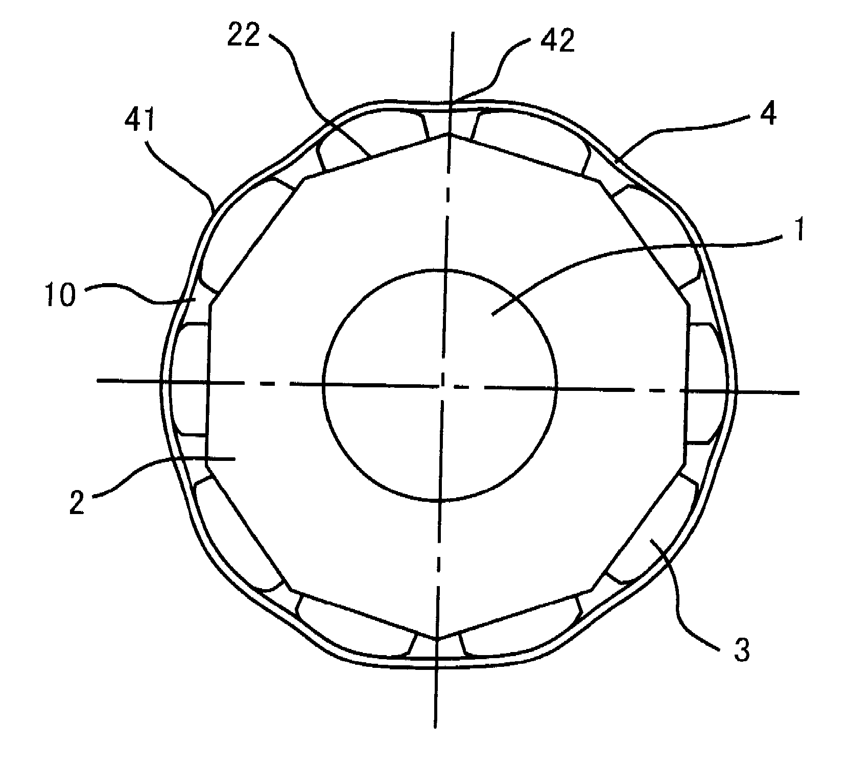
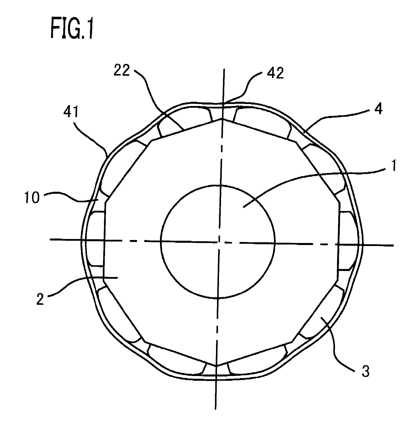
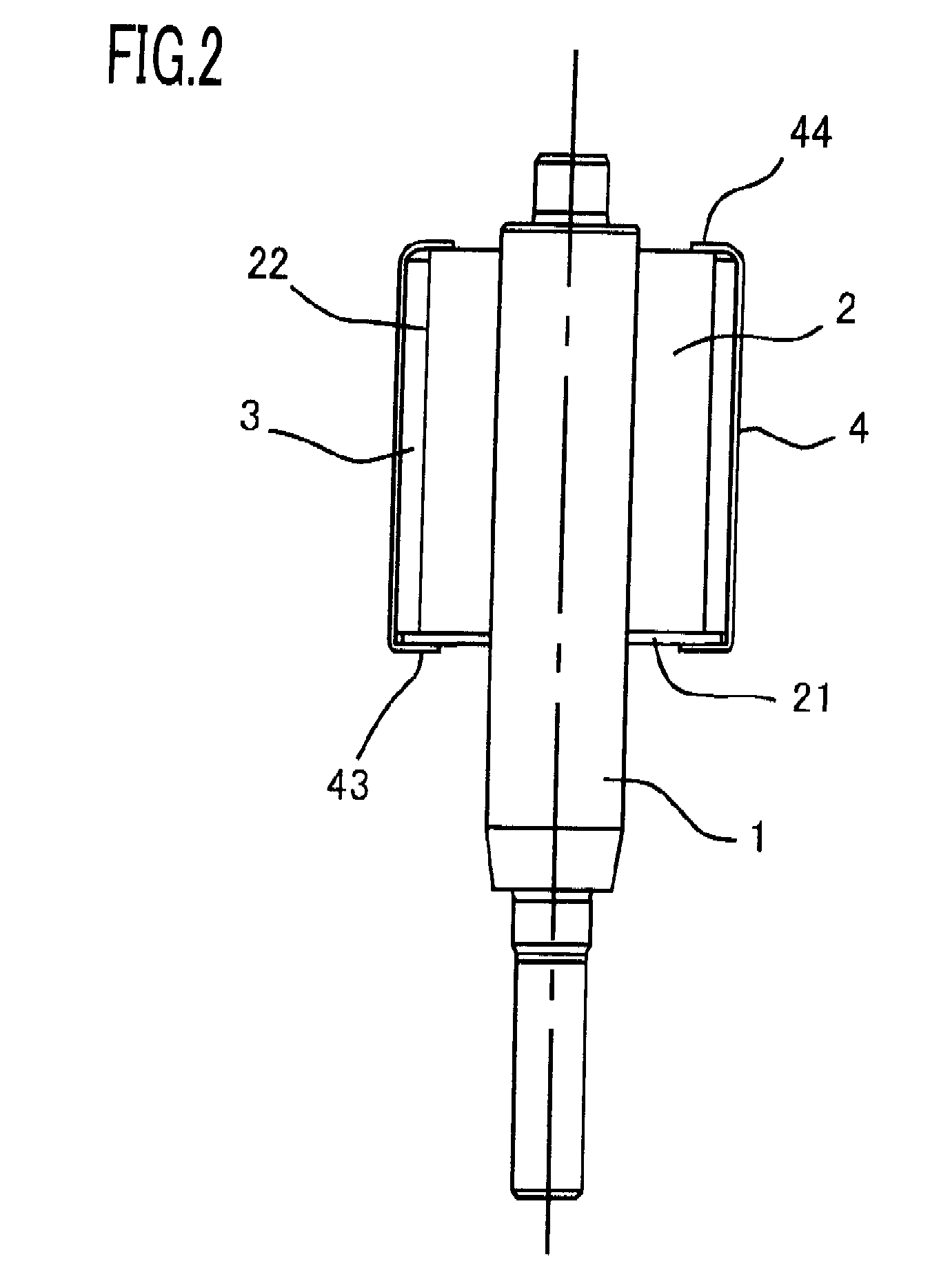
[0041]A rotor of a rotating electrical machine according to Embodiment 1 of the present invention will be explained below with reference to FIGS. 1 to 3. FIG. 1 is an explanatory transverse cross-sectional view of a rotor of a rotating electrical machine according to Embodiment 1 of the present invention; FIG. 2 is an explanatory longitudinal cross-sectional view illustrating the rotor; FIG. 3 is an explanatory transverse cross-sectional view illustrating the rotor. In FIGS. 1 and 2, a rotor shaft 1 of an rotating electrical machine is pivotably supported by bearings (unillustrated) each provided in a pair of brackets (unillustrated). A rotor iron core 2, which is tubularly configured with ring-shaped magnetic thin plates laminated in the radial direction, and the rotor shaft 1, which is inserted into the central through-hole of the rotor iron core 2 through press fitting method or the like, are integrally fixed to each other.

[0042]An end plate 21 is fixed on one axis-direction end ...

embodiment 2

[0055]Next, a rotor of a rotating electrical machine according to Embodiment 2 of the present invention will be explained with reference to FIGS. 4 and 5. FIG. 4 is an explanatory transverse cross-sectional view of a rotor of a rotating electrical machine according to Embodiment 2 of the present invention; FIG. 5 is a partially enlarged explanatory transverse cross-sectional view illustrating the rotor. In FIG. 4, the shape of an aluminum-made non-magnetic ring 4, disposed on the outer circumferential surfaces of magnetic poles 3 formed of a permanent magnet, is formed in such a way that the inner circumferential surface thereof lies on a tangential line 12 that passes on the outer circumferential surfaces of the magnetic poles 3 that are adjacent to each other or on a line that is shifted from the tangential lime 12 toward the rotor iron core 2. In other words, as illustrated in FIG. 5, the distance d, in the radial direction of the rotor iron core 2, between the tangential line 12...

embodiment 3

[0059]Next, a rotor of a rotating electrical machine according to Embodiment 3 of the present invention will be explained with reference to FIG. 6. FIG. 6 is an explanatory transverse cross-sectional view of a rotor of a rotating electrical machine according to Embodiment 3 of the present invention. In Embodiments 1 and 2, the positional restriction on the magnetic pole 3 is realized by the adhesive power, through an adhesive, between a magnetic-pole fixing portion 22 of a rotor iron core 2 and a magnetic pole 3 and by the circumferential-direction positional restriction force of a non-magnetic ring 4; however, in the rotor of a rotating electrical machine according to Embodiment 3, positioning mechanisms that restrict the circumferential-direction positions of the magnetic poles 3 are provided in the rotor iron core 2.

[0060]In other words, in FIG. 6, each of positioning mechanisms 6 is constituted with a protrusion member that extends on the outer circumferential surface of the rot...


PUM

PropertyMeasurementUnit
angleaaaaaaaaaa
angleaaaaaaaaaa
bending angleaaaaaaaaaa

Abstract

A rotor of a rotating electrical machine is provided in which neither deterioration nor fluctuation in the cogging torque is caused and that causes neither physical enlargement nor cost increase. The rotor of a rotating electrical machine, provided with a plurality of magnetic poles 3 that are fixed on a rotor iron core 2 and arranged spaced apart from one another in the circumferential direction of the rotor iron core 2, is characterized by including a tube-shaped non-magnetic ring 4 mounted on the outer circumferential surfaces of the plurality of magnetic poles 3, and characterized in that the non-magnetic ring has a plurality of inner-diameter bulging portions 41 that abut on the corresponding outer circumferential surfaces of the plurality of magnetic poles.

Description

BACKGROUND OF THE INVENTION[0001]1. Field of the Invention[0002]The present invention relates to a rotor, having a plurality of magnetic poles, of a rotating electrical machine and to a manufacturing method for the rotor.[0003]2. Description of the Related Art[0004]With regard to a rotor, of a rotating electrical machine, having a plurality of permanent magnets on the circumferential surface of a laminated iron core fixed on the circumferential surface of the rotor shaft, a configuration has already been proposed in which both axis-direction ends of each of the permanent magnets are covered with a cover of a non-magnetic material (e.g., refer to Patent Document 1.).[0005]In the conventional rotor of a rotating electrical machine, hereinafter) disclosed in Patent Document 1, the non-magnetic cover provided on the rotor is fixed on the permanent magnet, by means of an adhesive. With the conventional rotor of a rotating electrical machine configured in this manner, the position, in the...

Claims


Application Information

Patent Timeline
Patent Type & Authority Applications(United States)
IPC IPC(8): H02K1/28H02K1/27
CPCY10T29/49012H02K1/278H02K1/2781H02K1/22H02K15/00
Inventor YAMAMURA, AKIHIROASAO, YOSHIHITOAKUTSU, SATORUTAKASHIMA, KAZUHISA
Owner MITSUBISHI ELECTRIC CORP
Why Eureka
Try Eureka