

Optical recording method, optical recording apparatus, optical recording medium, and optical recording and reproducing method
- Summary
- Abstract
- Description
- Claims
- Application Information
AI Technical Summary
Benefits of technology
Problems solved by technology
Method used
Image

Examples
specific examples of embodiment
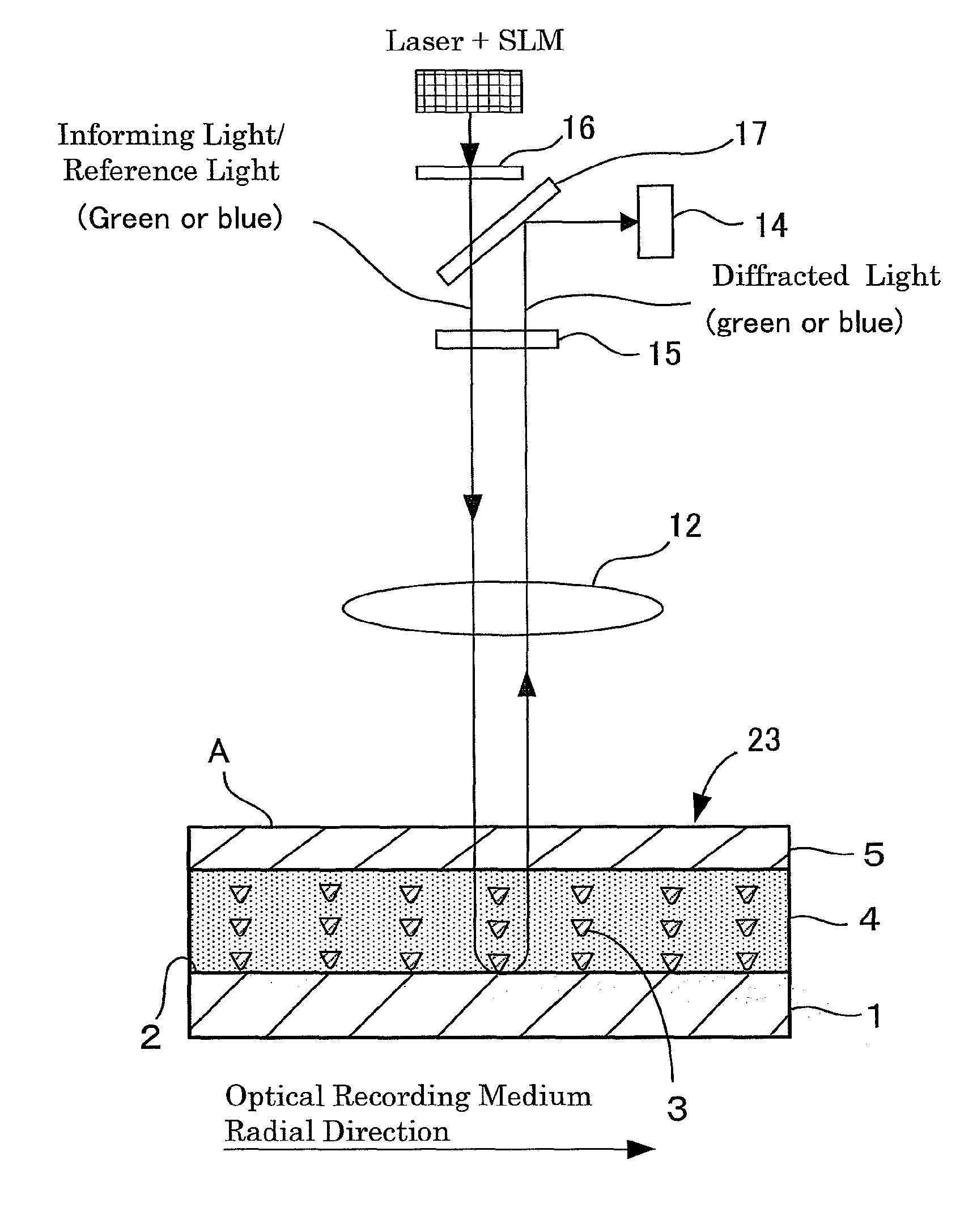
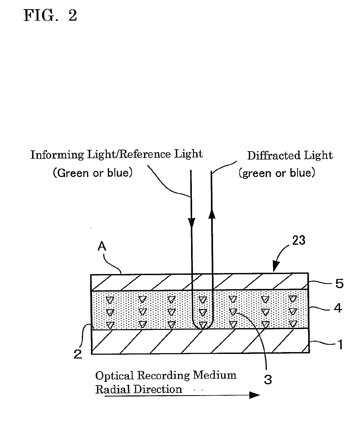
[0130]FIG. 2 is a schematic cross-sectional view showing configuration of a specific example of the optical recording medium 23 of an inventive embodiment. In the optical recording medium 23 according to the first embodiment, the surface of the substrate 1 made of polycarbonate resin or glass is coated with Al, Au, Pt or the like to form a reflective film 2.
[0131]When the gap layer is formed in the specific example of the embodiment, the gap layer may be formed by applying a UV curable resin or the like on the reflective film 2 of the second substrate 1 by spin coating or the like. The gap layer is effective for protecting the reflective film 2 and also for adjusting the size of holograms created in recording layer 4. Specifically, the interference region between the recording / reference light and the informing light requires a level of size in the recording layer 4, the gap layer is effectively provided between the recording layer 4 and the reflective film 2.
[0132]The recording laye...
example 1
[0154]An optical recording medium can be produced in order to carry out the inventive optical recording method.
Production of Optical Recording Medium
[0155]The resulting optical recording medium may comprise a first substrate, a second substrate, and a recording layer.
[0156]The second substrate may be a conventional polycarbonate resin substrate used for DVD+RW of diameter 120 mm and board thickness 0.6 mm. A reflective film is formed on the surface of the substrate. The material of the reflective film may be aluminum (Al).
[0157]An Al reflective film of 200 nm thick is formed by a DC magnetron sputtering process. A polycarbonate film of 100 μm thick is used as a gap layer on the reflective film and may be adhered by a UV curable resin.
[0158]The photopolymer coating liquid of the ingredients below may be prepared as the material of the recording layer.
Ingredients of Photopolymer Coating Liquiddi(urethaneacrylate) oligomer *1)59parts by massisobornyl acrylate30parts by massvinyl benzoa...
PUM
 Abstract
Description
Claims
Application Information