
Protocol for reliable, self-organizing, low-power wireless network for security and building automation systems

a wireless network and security and building automation technology, applied in the field of wireless network sensors and actuators, can solve the problems of substantial cost of implementation of such networks, and achieve the effects of low power consumption, low cost, and low cos

Active Publication Date: 2009-04-23
ROBERT BOSCH GMBH
View PDF24 Cites 18 Cited by
  • Summary
  • Abstract
  • Description
  • Claims
  • Application Information

AI Technical Summary

Benefits of technology

The present invention describes a way to wirelessly network sensors and actuators for surveillance and control using a hierarchical system architecture with multiple types of nodes. This avoids a single point of failure and allows for distributed control of the entire network. The sensor / actuator nodes form an ad-hoc multi-hop network with each other and with the cluster heads, which may be battery-operated and energy-efficient. The protocol also allows for low power consumption, rapid forwarding of occasional urgent messages, and continuous improvement of the network quality. The sensor / actuator node network may arrange itself based on global information about link quality and connectivity shared and processed at the cluster heads. User interaction during the setup or detailed planning may not be required. In case of link or node failures, the protocol may allow for automatic reconfiguration to ensure connectivity between the majority of the devices throughout the operational lifetime of the system.

Problems solved by technology

However, a substantial amount of the cost to implement such networks may include, for example, planning the network, installing the network elements, and configuring / reconfiguring the arrangement of network elements.
Furthermore, such networks may include battery-powered devices that may impose restrictions regarding resource consumption and / or network topology constraints.

Method used


Image

  • Protocol for reliable, self-organizing, low-power wireless network for security and building automation systems
  • Protocol for reliable, self-organizing, low-power wireless network for security and building automation systems
  • Protocol for reliable, self-organizing, low-power wireless network for security and building automation systems

Examples


Embodiment Construction

[0015]In the following description, the term “sensor node” may be used to collectively refer to both sensor nodes and actuator nodes. Likewise, the term “sensor node network” may be use to collectively refer to networks consisting of sensors and / or actuators. Communications within the sensor node network may be based on carrier sense multiple access (CSMA) with randomized back-off. Transmitted packets may include a preamble as defined by the physical layer, as well as a start symbol and control bytes, a packet type, a packet length, source and / or destination node identifiers, and a cyclic redundancy check (CRC). Optionally, transmission may be secured via link layer encryption with the exchange of a shared key, and authenticated with a message authentication code (MAC).

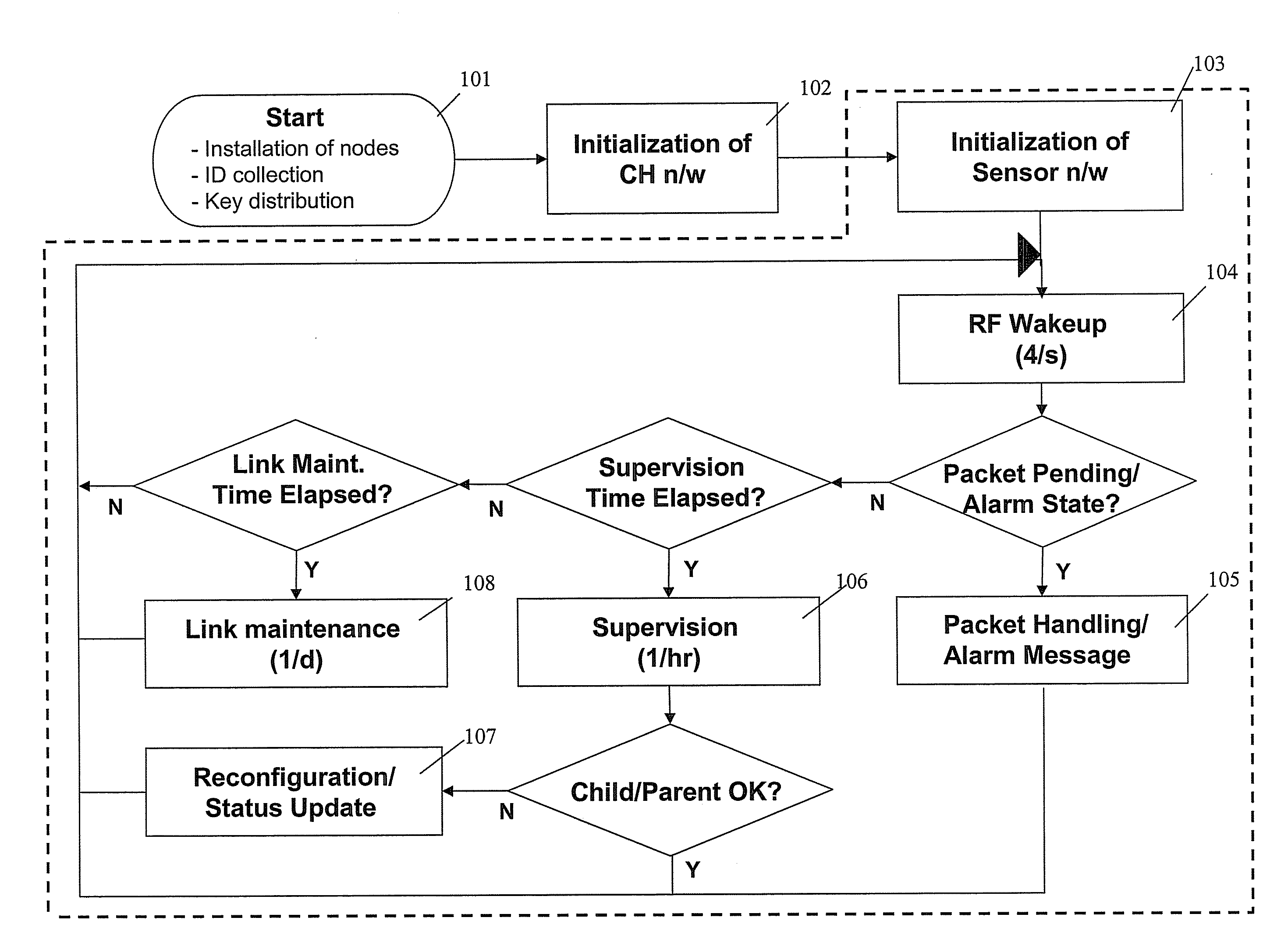
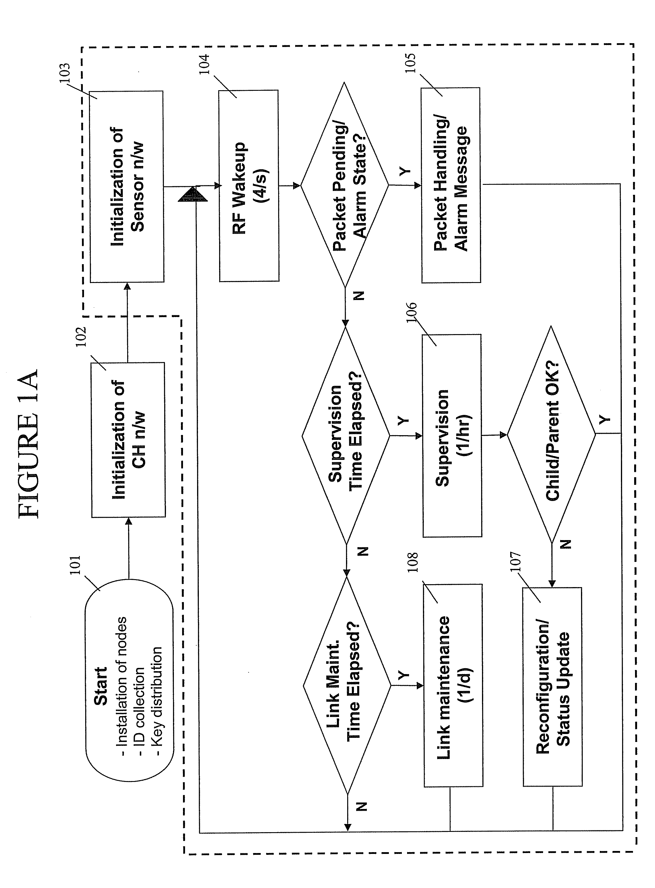
[0016]FIG. 1A is a flow chart representing an exemplary protocol method to wirelessly network sensors and / or actuators. In step 101, the network nodes are installed, unique identifiers (IDs) of the nodes are collected...


PUM


Abstract

A method to wirelessly network a sensor / actuator node is described. The sensor / actuator node is installed in a sensor / actuator node network and arranged in a hierarchical manner with a plurality of node levels and a cluster head network. A unique node identifier is assigned to the sensor node and the sensor node network is initialized. The sensor node is woken-up to perform a task and then set to an active low power mode.

Description

CROSS-REFERENCE TO RELATED APPLICATIONS[0001]This application is a divisional of prior U.S. patent application Ser. No. 10 / 301,478, filed on Nov. 21, 2002, which claims priority to U.S. Provisional Patent Application Ser. No. 60 / 347,569, filed on Jan. 10, 2002, all of which are incorporated herein by reference, in their entirety.FIELD OF THE INVENTION[0002]The present invention describes a protocol to wirelessly network sensors and actuators for surveillance and control.BACKGROUND INFORMATION[0003]Networks may be applied for surveillance and control. However, a substantial amount of the cost to implement such networks may include, for example, planning the network, installing the network elements, and configuring / reconfiguring the arrangement of network elements. Furthermore, such networks may include battery-powered devices that may impose restrictions regarding resource consumption and / or network topology constraints.SUMMARY OF THE INVENTION[0004]The present invention describes a ...

Claims


Application Information

Patent Timeline
Patent Type & Authority Applications(United States)
IPC IPC(8): H04L12/28H04B7/24H04L12/12H04L12/56H04L29/06H04W4/00
CPCH04L12/12H04L12/2803H04L12/2827H04W52/0245H04W52/0216H04W52/0219H04W52/0229H04W84/18H04Q9/00H04Q2209/883Y02D30/70
Inventor HERRMANN, FALKMANJESHWAR, ARATIHILL, JASON
Owner ROBERT BOSCH GMBH
Learn More