Control of clearance at blade tips in a high-pressure turbine of a turbine engine

a turbine engine and high-pressure turbine technology, which is applied in the direction of machines/engines, efficient propulsion technologies, liquid fuel engines, etc., can solve the problems of reducing radial clearance, slow movement due to thermal expansion of the rotor disk, and reducing the effect of radial clearan

Active Publication Date: 2009-04-23
SN DETUDE & DE CONSTR DE MOTEURS DAVIATION S N E C M A
View PDF8 Cites 14 Cited by
  • Summary
  • Abstract
  • Description
  • Claims
  • Application Information

AI Technical Summary

Benefits of technology

[0008]The invention is intended in particular to provide a simple, economical and effecti

Problems solved by technology

Indeed, the movements due to thermal expansion of the rotor disk are slow during the passage from the full rate of speed to the slowed rate of speed due to the large mass of the disk and the resulting long thermal response time; as the mass of the elements of the stator is lower, their thermal response is faster.
The centrifugal force resulting from the acceleration causes an additional expansion of the rotor, correspondingly redu

Method used


Image

  • Control of clearance at blade tips in a high-pressure turbine of a turbine engine
  • Control of clearance at blade tips in a high-pressure turbine of a turbine engine
  • Control of clearance at blade tips in a high-pressure turbine of a turbine engine

Examples


Embodiment Construction

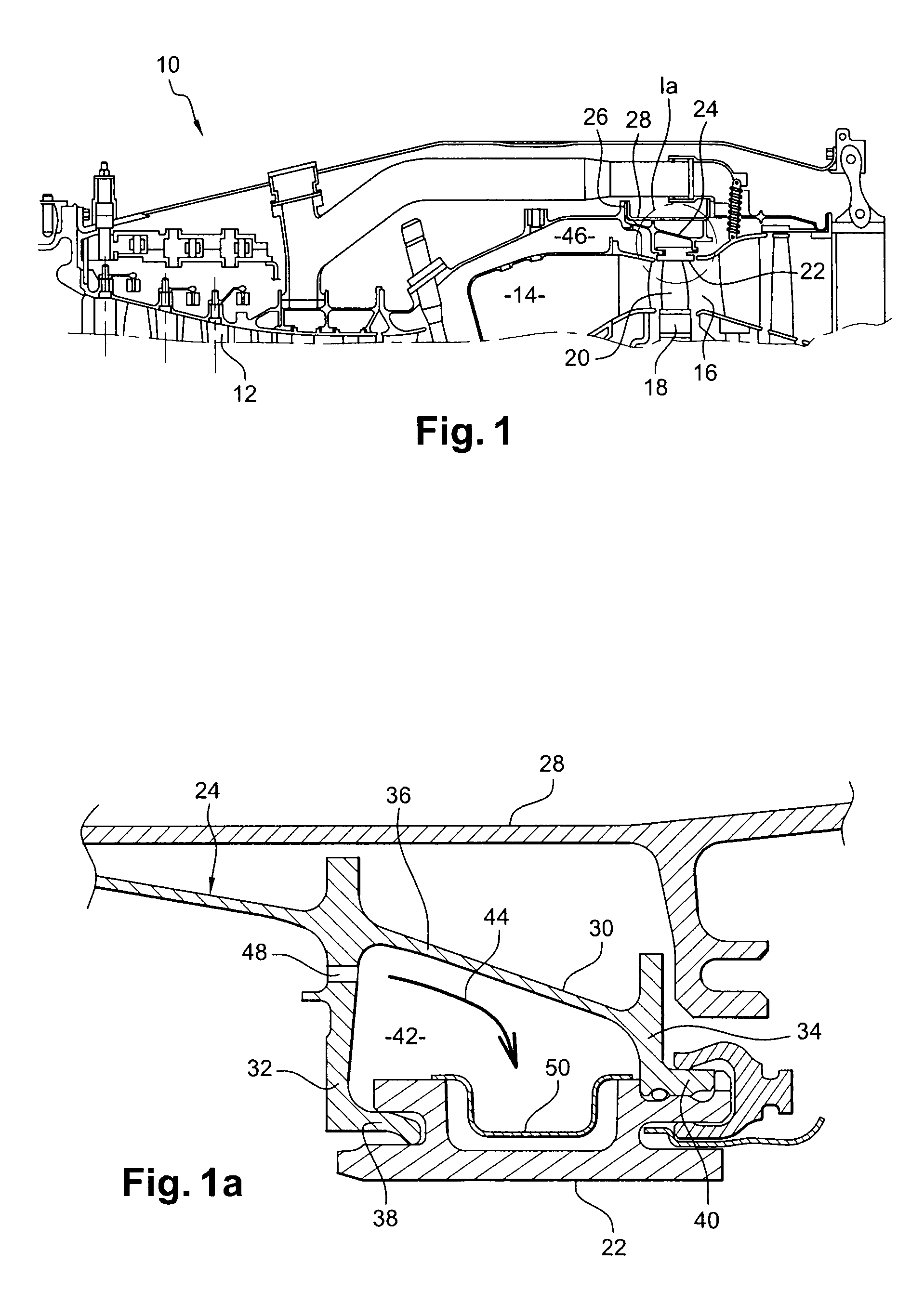
[0038]FIG. 1 shows a portion of a turbine engine 10 of a known type, including, upstream to downstream, a compressor 12, a combustion chamber 14, and a gas turbine 16.

[0039]The turbine 16 comprises a high-pressure stage located immediately downstream of the combustion chamber 14 and intended to receive a hot gas flow from the combustion chamber and to provide these gases to one or more low-pressure stages before ejection. The high-pressure stage includes a rotor mounted on a shaft to which a high-pressure compressor rotor is coupled, while the low-pressure stage includes a rotor mounted on a shaft to which a fan located at the inlet of the turbine engine is coupled.

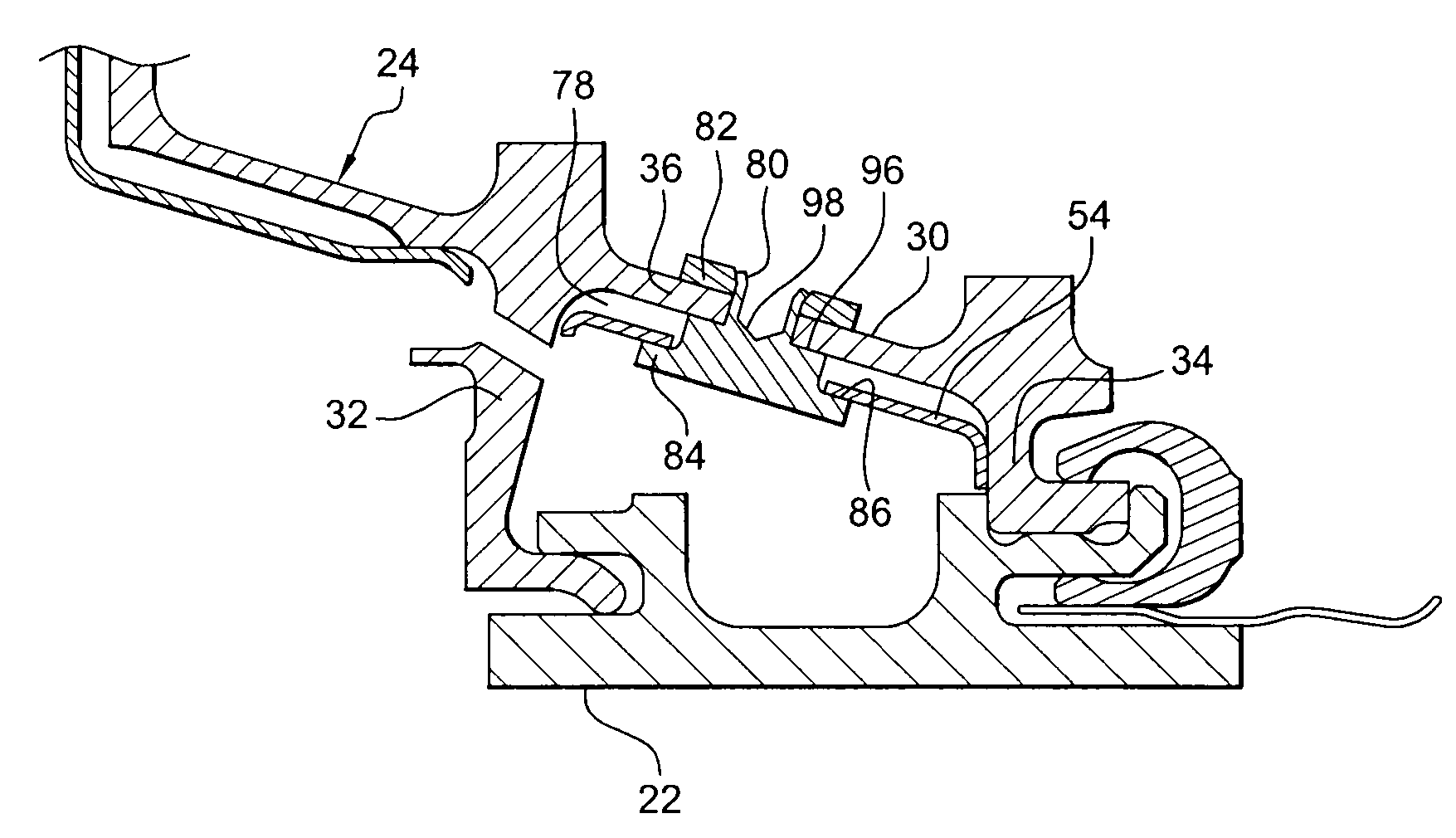
[0040]The rotor of the high-pressure turbine stage includes a disk 18 with mobile blades 20 extending radially from the periphery of the disk 18 and intended to drive the rotor by the force of the gases from the combustion chamber 14.

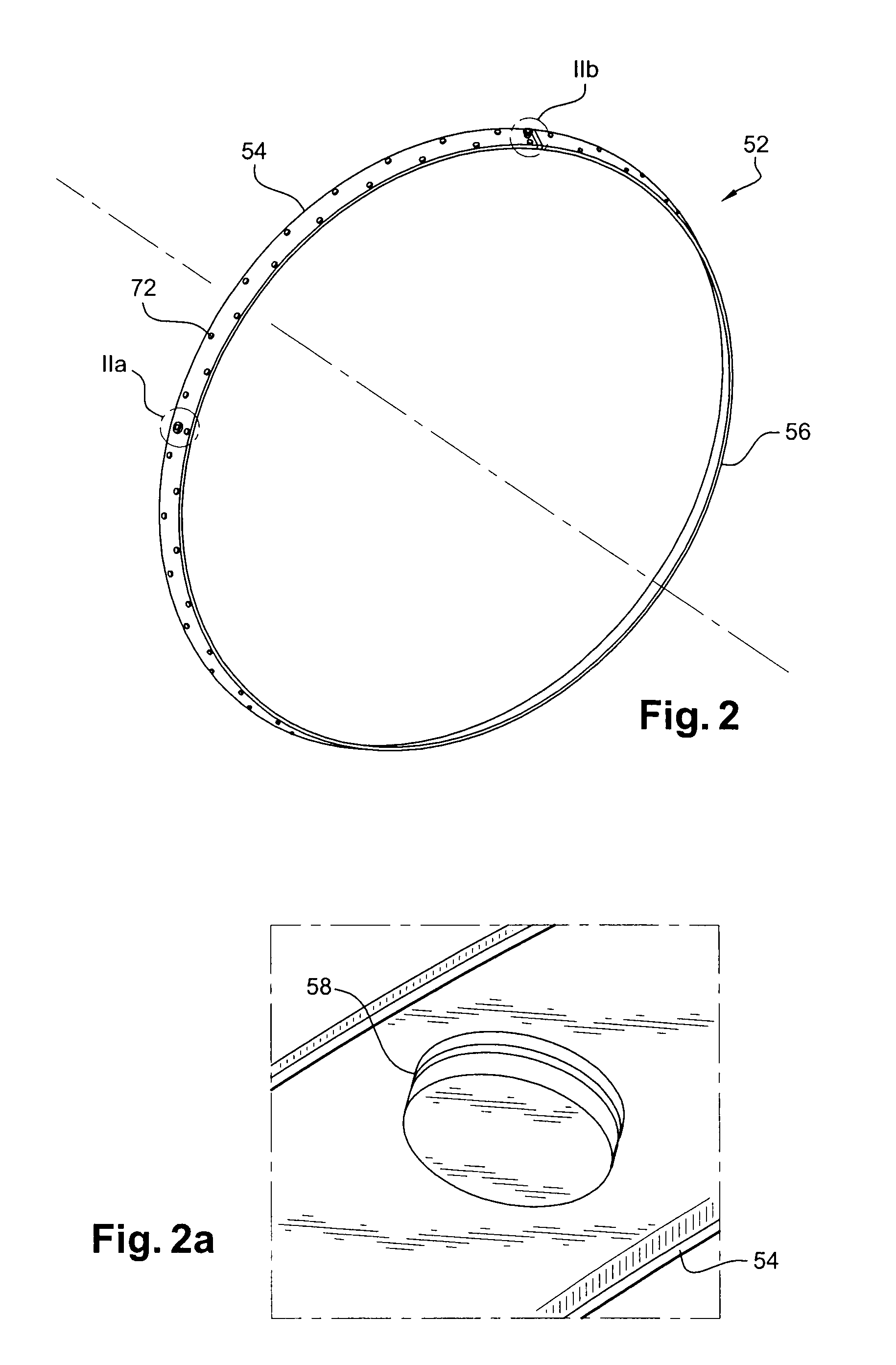
[0041]The disk 18 is surrounded by a sealing ring 22, which is formed by a plurality of a...


PUM


Abstract

Turbine stage in a turbine engine, including a wheel with blades rotating inside a sealing ring (22) held by a casing (24) of the turbine, and an annular thermal protection sheet mounted between the casing (24) and the ring (22), wherein the annular thermal protection sheet is formed by a plurality of curved plates (54, 56) mounted end-to-end and attached by pins (70) to the casing (24).

Description

[0001]This invention relates to a high-pressure turbine in a turbine engine, such as an airplane turbojet or turboprop engine.BACKGROUND OF THE INVENTION[0002]A turbine engine includes essentially a compressor, a combustion chamber and a turbine, in which the compressor supplies the combustion chamber with pressurised air, and the turbine receives the hot gases coming from the combustion chamber so as to extract energy therefrom. The stage of the turbine located immediately downstream of the combustion chamber, commonly called the high-pressure stage, includes a disk equipped with blades on its periphery and surrounded in general by a stationary sealing ring held by a casing.[0003]The radial clearance between the tips of the blades and the sealing ring must be as low as possible in order to minimise the passage of pressurised air outside of the zone swept by the blades and thus prevent the turbine performance from being hindered, but this radial clearance must be sufficient to avoid...

Claims


Application Information

Patent Timeline
IPC IPC(8): F01D11/18F02C7/24F01D25/14
CPCF01D11/005F05D2240/11Y02T50/671F01D11/24Y02T50/60
Inventor DAKOWSKI, MATHIEUDORIN, CLAIREGENDRAUD, ALAIN DOMINIQUEPOMMIER, NICOLAS
Owner SN DETUDE & DE CONSTR DE MOTEURS DAVIATION S N E C M A
Why Eureka
Try Eureka