Measurement of sound speed of downhole fluid utilizing tube waves

a technology of sound speed and downhole fluid, which is applied in the field of subterranean formation analysis, can solve problems such as problems such as problems such as problems such as problems such as problems such as problems such as problems such as problems such as difficulty in measuring the sound speed of downhole fluid outside the borehole, and achieves the effects of improving measurement accuracy, facilitating adaptation, and facilitating typical tube geometry

Active Publication Date: 2009-04-23
SCHLUMBERGER TECH CORP
View PDF14 Cites 18 Cited by
  • Summary
  • Abstract
  • Description
  • Claims
  • Application Information

AI Technical Summary

Benefits of technology

[0008]One advantage of using tube waves to measure sound speed of downhole fluids is that typical tube geometry is simple and relatively easy to be adapted to wireline and LWD tool geometry. Also, the tube can be made part of a flow line, which helps to keep the test volume filled with local fluid, i.e., such that its constituents have not been contaminated, in comparison with a sample that is transported to the surface. Measurement accuracy is enhanced because, at the time of measurement, the fluid is subject to ambient conditions of the location, e.g., temperature, pressure, and gas influx.
[0009]Another advantage is that tube waves, being the lowest order mode in a fluid-filled tube, i.e., being the dominant mode at low frequencies, are relatively easy to excite and detect.
[0010]Another advantage of using tube waves is that the tube wave speed is measured over a length scale of wavelength, which is significantly, up to one order of magnitude, greater than the ID of the tube. This relatively large test volume will reflect heterogeneities such as small solid particles, cuttings, or gas bubbles in the volume averaged speed instead of large fluctuations in time.

Problems solved by technology

However, measuring the sound speed of downhole fluids outside the borehole can be problematic because the sound speed of a fluid is a function of its constituents, temperature and pressure.

Method used


Image

  • Measurement of sound speed of downhole fluid utilizing tube waves
  • Measurement of sound speed of downhole fluid utilizing tube waves
  • Measurement of sound speed of downhole fluid utilizing tube waves

Examples


Embodiment Construction

[0027]The particulars shown herein are by way of example and for purposes of illustrative discussion of the embodiments of the present invention only and are presented in the cause of providing what is believed to be the most useful and readily understood description of the principles and conceptual aspects of the present invention. In this regard, no attempt is made to show structural details of the present invention in more detail than is necessary for the fundamental understanding of the present invention, the description taken with the drawings making apparent to those skilled in the art how the several forms of the present invention may be embodied in practice. Further, like reference numbers and designations in the various drawings indicated like elements.

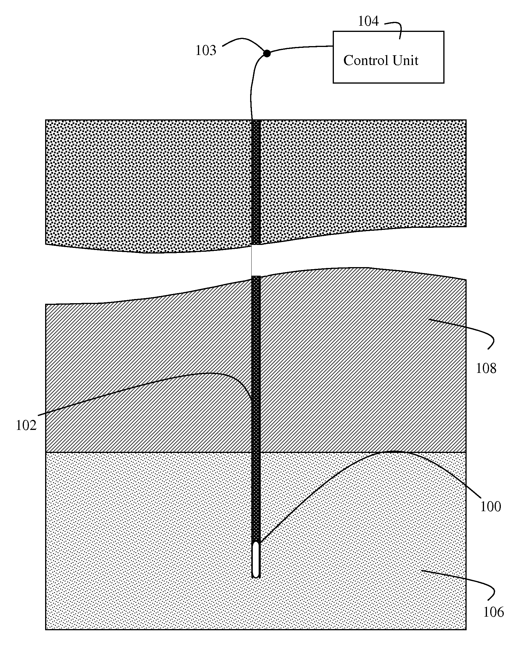
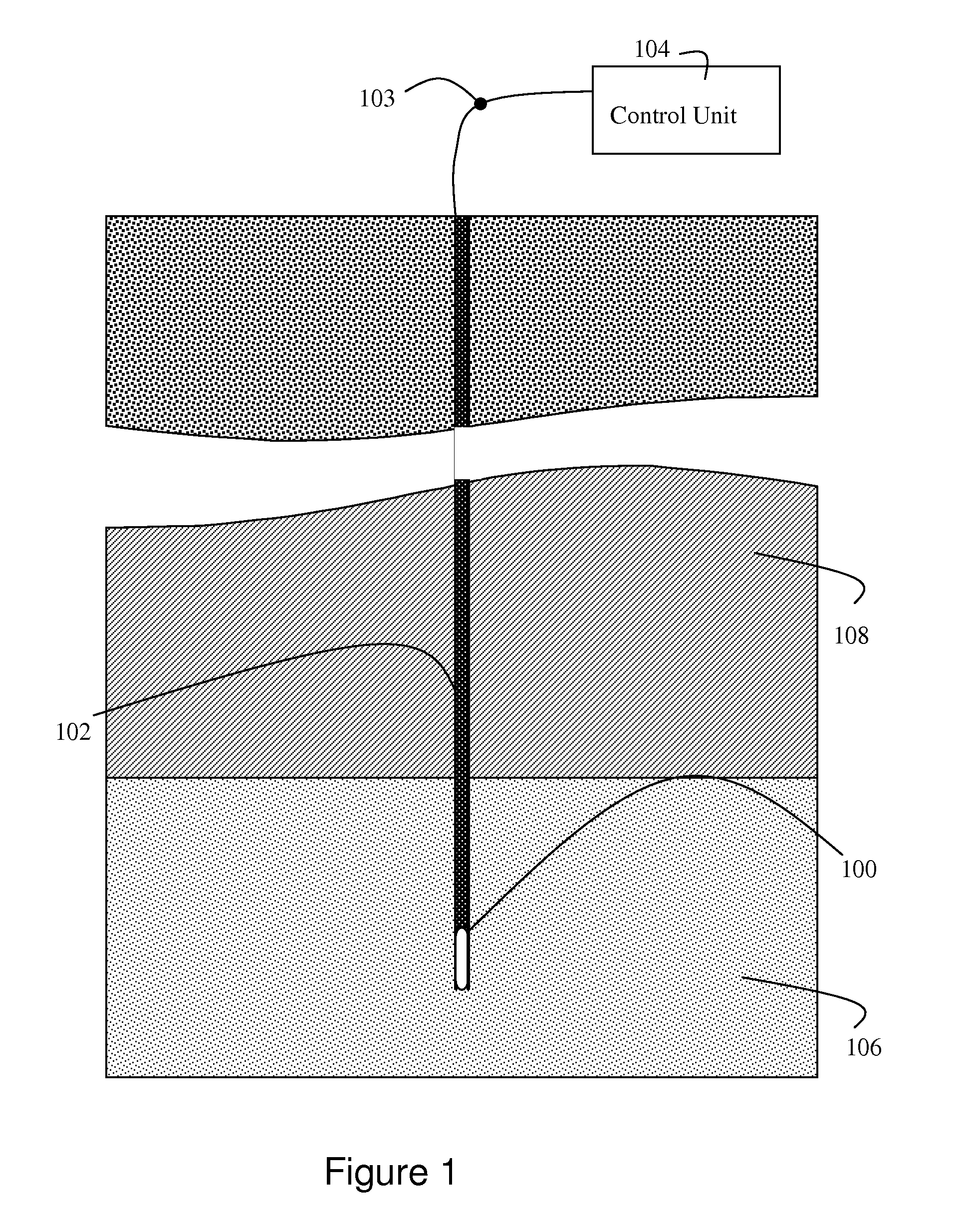
[0028]The present invention is directed to an apparatus for facilitating analysis of a subterranean formation. The apparatus can comprise of a tube having the inside filled with a downhole fluid. The apparatus further can inc...


PUM


Abstract

A technique for utilizing tube waves to measure sound speed of fluids and other properties in the frequency range of about 5 to 100 kHz. A drill string is equipped with a sensor tube having a cavity filled with a downhole fluid such as borehole mud or formation fluid. An acoustic transmitter and an array of acoustic receivers are mounted on the tube in direct contact with the fluid. Processing circuitry calculates a property, e.g., sound speed, of the fluid based on time-of-flight of an acoustic signal generated by the transmitter and received by the array of receivers. Alternatively change in signal phase as a function of frequency may be employed by the processing circuitry. The technique is particularly suited to measuring the sound speed of borehole mud in situ.

Description

BACKGROUND OF THE INVENTION[0001]1. Field of the Invention[0002]This invention is generally related to analysis of subterranean formations, and more particularly to measurement of the speed of sound in a downhole fluid in order to facilitate acoustic logging operations for formation evaluation and reservoir characterization.[0003]2. Background of the Invention[0004]Wireline and logging-while-drilling (LWD) tools are used to measure physical, chemical, and structural characteristics of formations surrounding a borehole. For example, data gathered by logging tools can be used to interpret formation stratigraphy, lithology, mineralogy, and pore fluid content. Logging tools typically emit one or more of an acoustic, electromagnetic and optical signal, and measure the response to that signal. In the case of acoustic logging tools, changes in amplitude, phase and speed can be utilized to characterize the formation. Some acoustic logging tools utilize modal propagations, such as Stoneley, ...

Claims


Application Information

Patent Timeline
Patent Type & Authority Applications(United States)
IPC IPC(8): G01V1/28
CPCE21B49/081E21B49/10G01N29/024G01V1/44G01N2291/02416G01N2291/103G01N2291/012G01H5/00
Inventor HSU, CHAUR-JIAND'ANGELO, RALPH M.
Owner SCHLUMBERGER TECH CORP
Why Eureka
Try Eureka