Dynamics simulation device, dynamics simulation method, and computer program

a simulation device and dynamics technology, applied in the field of dynamics simulation devices, can solve the problems of large calculation cost, unstable situation, and increase in calculation cost with the increase in the number of collision points between the cubes, and achieve the effect of low calculation cost and high precision

Inactive Publication Date: 2009-04-23
SONY CORP
View PDF2 Cites 19 Cited by
  • Summary
  • Abstract
  • Description
  • Claims
  • Application Information

AI Technical Summary

Benefits of technology

[0026]It is desirable to provide a dynamics simulation device, a dynamics simulation method, and a computer program that can calculate the contact force or collision force acting between rigid bodies contacting or colliding with each other with high precision and low calculation cost.
[0028]It is also desirable to provide a dynamics simulation device, a dynamics simulation method, and a computer program that can calculate a force f acting on a collision point with high precision and at a high speed, by solving a linear complementary problem after calculating an operational space inertial inverse matrix Λ−1.
[0034]However, since the operational space inertial inverse matrix Λ−1 is a square matrix having the total number of repulsive forces as the order, the calculation cost for the calculation is great. When it is intended to solve the linear complementary problem using the analysis type method, the repulsive force is calculated strictly and thus the stability in numerical calculation is high. However, the simulation speed is lowered with the increase in the number of collision points between the cubes.
[0044]According to the embodiments of the invention, it is possible to provide a dynamics simulation device, a dynamics simulation method, and a computer program that can calculate the contact force or collision force acting between rigid bodies contacting or colliding with each other in the rigidity dynamics simulation with high precision and low calculation cost.
[0046]According to the embodiments of the invention, it is also possible to provide a dynamics simulation device, a dynamics simulation method, and a computer program that can calculate a force f acting on a collision point with high precision and at a high speed, by solving a linear complementary problem after calculating an operational space inertial inverse matrix Λ−1
[0047]In the dynamics simulation device according to the above-mentioned embodiment of the invention, since all or a part of the calculation of the operational space inertial inverse matrix Λ−1 which is a bottleneck of the analysis type method or the solution of the linear complementary problem are replaced with the disturbance observer and a simply feedback control system based on the robust control, the stability in numerical calculation and the decrease in calculation cost can be both accomplished. Accordingly, it is possible to enhance the speed of the entire rigidity dynamics simulation and thus to carry out the dynamics simulation on complex systems in real time.

Problems solved by technology

On the contrary, when the value of the vertical repulsive force fN is too great, the cubes get apart from each other to cause the numerical divergence in some cases, thereby making the situation unstable.
The operational space inertial inverse matrix Λ−1 is a square matrix having the total number of repulsive forces (in other words, the total number of collision points between cubes) as an order, but the calculation cost for the calculation is great.
The calculation cost increases with the increase in the number of collision points between the cubes.
However, there is a problem in that the simulation decreases in speed with the increase in the number of collision points between the cubes.
However, when it is intended to simulate the collision between the rigid bodies by the use of the penalty method, it is necessary to insert very strong spring and damper in FIG. 10, thereby easily causing the numerical divergence.

Method used


Image

  • Dynamics simulation device, dynamics simulation method, and computer program
  • Dynamics simulation device, dynamics simulation method, and computer program
  • Dynamics simulation device, dynamics simulation method, and computer program

Examples


Embodiment Construction

[0059]Hereinafter, the embodiments of the invention will be described in detail with reference to the accompanying drawings.

[0060]The invention relates to dynamics simulation for allowing a computer to reproduce physical interactions such as collision and contact between objects in a space where plural objects coexist, and can be applied to a virtual reality (VR) system displaying a sense of force or a tactile sense for a manipulator, in addition to visual information and audio information.

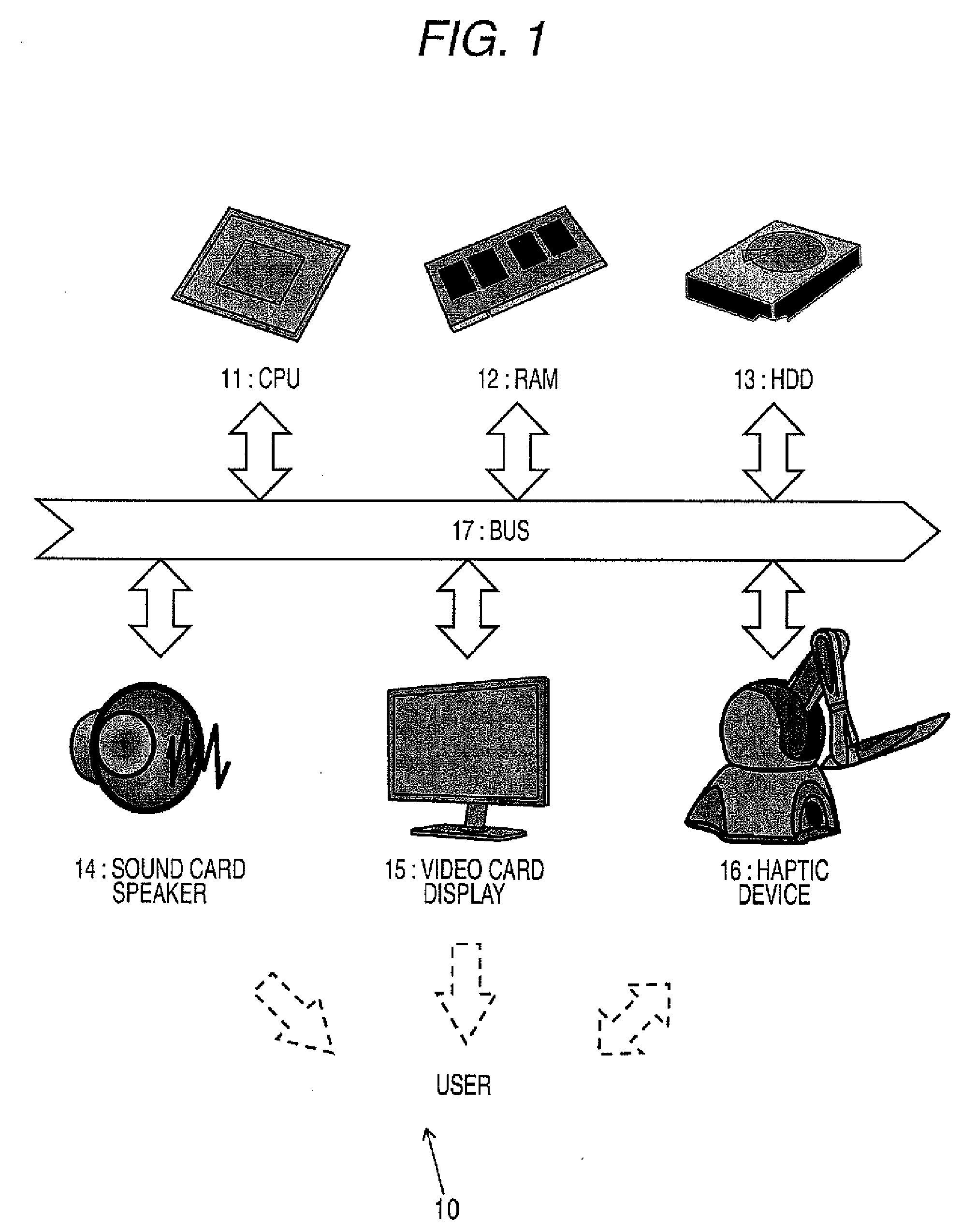
[0061]FIG. 1 schematically shows a configuration of a VR system 10. The VR system 10 displays a shape of a 3D space constructed in a computer for a user through a speaker 14, a display 15, a mouse (not shown), a force displayer (haptic device) 16.

[0062]The speaker 14 displays sound relating to events occurring in a 3D space (virtual reality space or telepresence space), the display 14 displays visual information of the 3D space, and the haptic device 16 displays the sense of force felt at the time...


PUM


Abstract

A dynamics simulation device for dynamically simulating physical interactions acting on a plurality of objects under an environment where the objects coexist is disclosed. The device includes: nominal value providing means for providing a nominal value Λn of an operational space inertial matrix; nominal inertial force calculating means for calculating a nominal inertial force acting on the operational space by the use of the nominal value Λn of the operational space inertial matrix and a target acceleration value of the physical quantity x; a disturbance observer estimating forces other than the nominal inertial force acting on the operational space as a disturbance; and means for calculating the force f acting on the physical quantity on the basis of the nominal inertial force and the estimated disturbance fd.

Description

CROSS REFERENCES TO RELATED APPLICATIONS[0001]The present invention contains subject matter related to Japanese Patent Application JP 2007-272097 filed in the Japanese Patent Office on Oct. 19, 2007, the entire contents of which is incorporated herein by reference.BACKGROUND OF THE INVENTION[0002]1. Field of the Invention[0003]The present invention relates to a dynamics simulation device, a dynamics simulation method, and a computer program for allowing a computer to reproduce a physical interaction of collision or contact between objects under a virtual reality environment or a telepresence environment in which plural objects coexist, and more particularly, to a dynamics simulation device, a dynamics simulation method, and a computer program for calculating a contact force or a collision force acting between rigid bodies contacting or colliding with each other in a rigid body dynamics simulation.[0004]More specifically, the invention relates to a dynamics simulation device, a dynam...

Claims


Application Information

Patent Timeline
Patent Type & Authority Applications(United States)
IPC IPC(8): G06F7/60G06F17/10G06F19/00
CPCG06F2217/16G06F17/5009G06F2111/10G06F30/20
Inventor NAGASAKA, KENICHIRO
Owner SONY CORP
Why Eureka
Try Eureka