Fluid supply connection for reductant delivery unit for selective catalytic reduction systems

a technology of catalytic reduction and fluid supply connection, which is applied in the direction of machines/engines, combustion types, lighting and heating apparatus, etc., can solve the problems of increasing the thaw times to thaw this volume, and the high nitrogen oxide emissions of lean-burn engines that are difficult to trea

Inactive Publication Date: 2009-04-30
CONTINENTAL AUTOMOTIVE SYST INC
View PDF17 Cites 33 Cited by
  • Summary
  • Abstract
  • Description
  • Claims
  • Application Information

AI Technical Summary

Benefits of technology

[0012]An object of the invention is to fulfill the needs referred to above. In accordance with the principles of the present invention, this objective is obtained by providing a reductant delivery unit for selective catalytic reduction (SCR) after-treatment for vehicles. The reductant delivery unit includes a solenoid fluid injector constructed and arranged to be associated with an exhaust gas flow path upstream of a SCR catalytic converter. The fluid injector has a fluid inlet and a fluid outlet. The fluid inlet being constructed and arranged to receive a source of urea solution and the fluid outlet being constructed and arranged to communicate directly with the exhaust flow path so as to control injection of urea solution into the exhaust gas flow path. Supply structure defines the fluid inlet. The supply structure includes a cup coupled to a body of the injector and a supply tube integral with the cup to define a single member. The supply tube is constructed and arranged to be coupled with the source of urea solution to deliver urea solution to the fluid inlet. The supply tube is constructed and arranged to be heated by a heat source so that an entire volume of the urea solution delivered to the

Problems solved by technology

Lean-burn engines exhibit high levels of nitrogen oxide (NOx) emissions that are difficult to treat in oxygen-rich exhaust environments characteristic of lean-burn combustion.
Ammonia is difficult to handle in its pure form in the automotive environment.
This connection results in an unheated volume (indicated by dimension A in FIG. 2) of fluid that is difficult to re

Method used


Image

  • Fluid supply connection for reductant delivery unit for selective catalytic reduction systems
  • Fluid supply connection for reductant delivery unit for selective catalytic reduction systems

Examples


Embodiment Construction

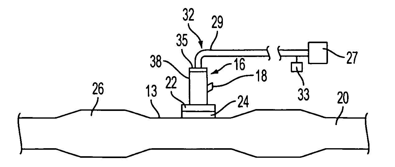
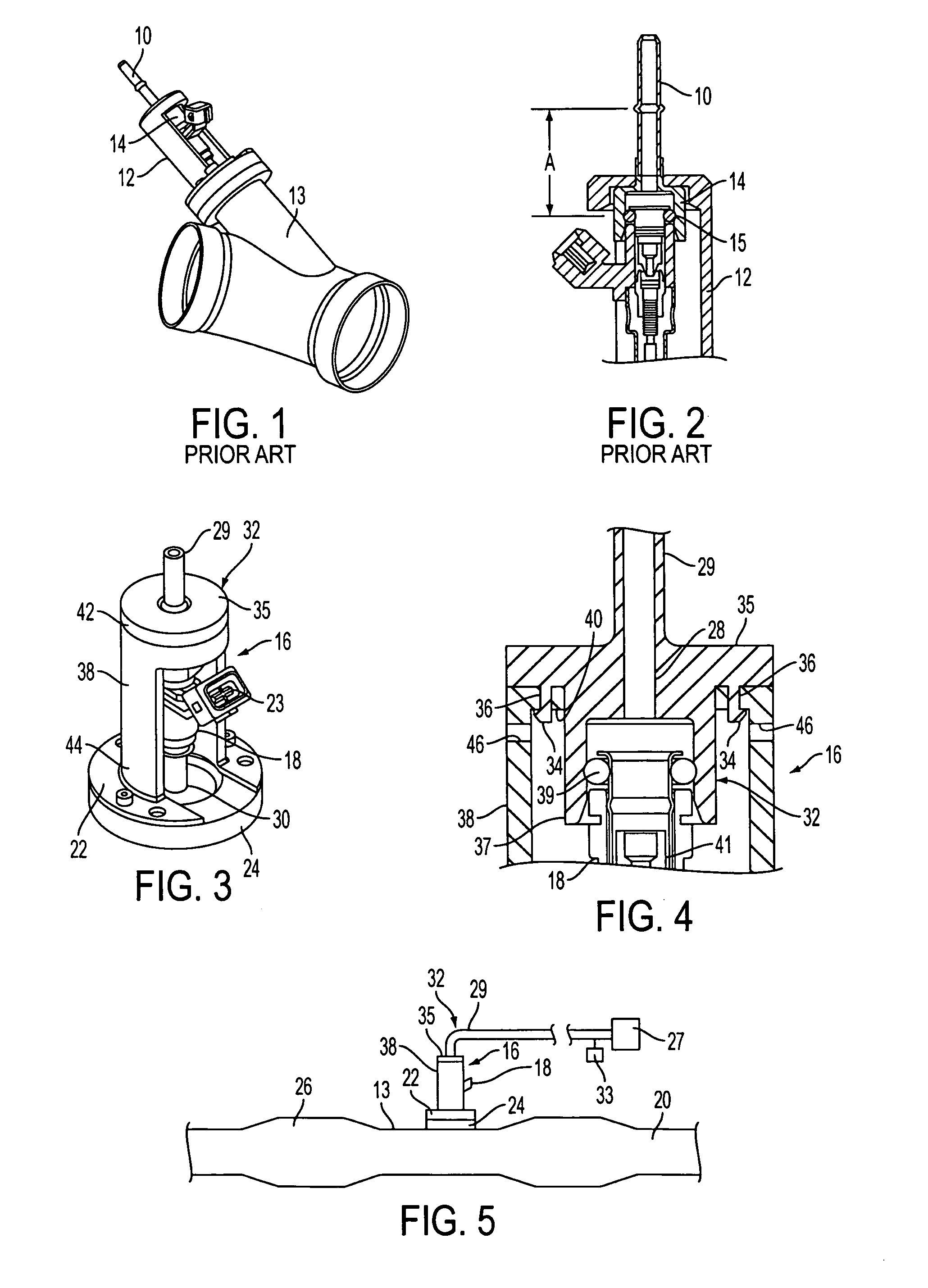
[0021]With reference to FIG. 3, a reductant delivery unit (RDU) for the delivery of AUS-32 to the engine exhaust is shown, generally indicated at 16, in accordance with an embodiment of the invention. The RDU 16 is used in SCR exhaust after-treatment systems on vehicles.

[0022]The metering function of the RDU 16 is performed by a specially adapted and packaged solenoid fluid injector 18. The injector 18 also provides the spray preparation of the fluid in the exhaust path 13 that is upstream of an SCR catalytic converter 20 (FIG. 5). More particularly, a flange 22 of the RDU 16 with injector 18 is mounted on a boss 24 of the exhaust path 13 preferably between an oxygen catalytic converter 26 and the SCR catalytic converter 20. An advantage of using the fluid injector 18 is a reduction in cost afforded by using a high volume automotive component.

[0023]The fluid injector 18 is preferably a gasoline, electrically operated, solenoid fluid injector such as the type disclosed in U.S. Pat. N...


PUM


Abstract

A reductant delivery unit (16) is provided unit for selective catalytic reduction (SCR) after-treatment for vehicles. The unit includes a solenoid fluid injector (18) associated with an exhaust gas flow path (13). The injector has a fluid inlet (28) and a fluid outlet (30) with the fluid inlet receiving a source of urea solution and the fluid outlet communicating directly with the exhaust flow path so as to control injection of urea solution into the exhaust gas flow path. Supply structure (32) defines the fluid inlet and includes a cup (37) coupled to a body (18) of the injector and a supply tube (29) integral with the cup to define a single member. The supply tube is coupled with the source (27) of urea solution to deliver urea solution to the fluid inlet. The supply tube is heated by a heat source (33) so that an entire volume of the urea solution delivered to the fluid inlet is heated.

Description

[0001]This application claims the benefit for priority purposes of the earlier filing date of U.S. Provisional Application No. 60 / 982,531, filed on Oct. 25, 2007, which is hereby incorporated by reference into this specification.FIELD OF THE INVENTION[0002]The invention relates to a reductant delivery unit (RDU) that supplies reductant to an engine exhaust system and, more particularly, to an improved fluid supply connection between a Selective Catalytic Reduction (SCR) injection unit and heated supply tube.BACKGROUND OF THE INVENTION[0003]The advent of a new round of stringent emissions legislation in Europe and North America is driving the implementation of new exhaust after-treatment systems, particularly for lean-burn technologies such as compression-ignition (diesel) engines, and stratified-charge spark-ignited engines (usually with direct injection) that are operating under lean and ultra-lean conditions. Lean-burn engines exhibit high levels of nitrogen oxide (NOx) emissions ...

Claims


Application Information

Patent Timeline
IPC IPC(8): F01N3/10
CPCF01N3/2066F01N2530/18F01N2610/02Y02T10/24F01N2610/14F01N2610/1453F01N2610/10Y02A50/20Y02T10/12
Inventor BUGOS, STEPHENVAN VUUREN, WILLEM NICOLAAS
Owner CONTINENTAL AUTOMOTIVE SYST INC
Why Eureka
Try Eureka