Limited Slip Differential For Electric Vehicle

a technology of electric vehicles and differentials, applied in the direction of battery/fuel cell control arrangements, sport apparatus, gearing, etc., can solve the problems and achieve the effect of difficult braking on slippery surfaces

Inactive Publication Date: 2009-04-30
TEXTRON INC
View PDF15 Cites 7 Cited by
  • Summary
  • Abstract
  • Description
  • Claims
  • Application Information

AI Technical Summary

Benefits of technology

[0005]The present invention utilizes the drive motor as a source of braking torque. However, braking on slippery surfaces can be difficult when the drive motor is used for providing braking torque. In cases where one wheel loses traction, the other wheel is free to turn, resulting in no braking torque being applied to either of the wheels. This can also happen when an electromechanical brake on the motor shaft is used for emergency braking or for parking. To prevent this problem, the present disclosure provides a limited slip differential mechanism for preventing and / or limiting relative movement between the wheels, thus providing braking torque. In other words, when the first and second output shafts of the differential are prevented from rotating relative to one another, and the input from the motor is braked, the differential is locked up and, therefore, the rear wheels are automatically prevented from rotating.

Problems solved by technology

Electric vehicle disc brake systems are specially designed due to the limited ground clearance of the electric vehicle which has smaller wheels than a standard automotive vehicle.
However, braking on slippery surfaces can be difficult when the drive motor is used for providing braking torque.

Method used


Image

  • Limited Slip Differential For Electric Vehicle
  • Limited Slip Differential For Electric Vehicle
  • Limited Slip Differential For Electric Vehicle

Examples


Embodiment Construction

[0012]The following description is merely exemplary in nature and is not intended to limit the present disclosure, application, or uses. It should be understood that throughout the drawings, corresponding reference numerals indicate like or corresponding parts and features.

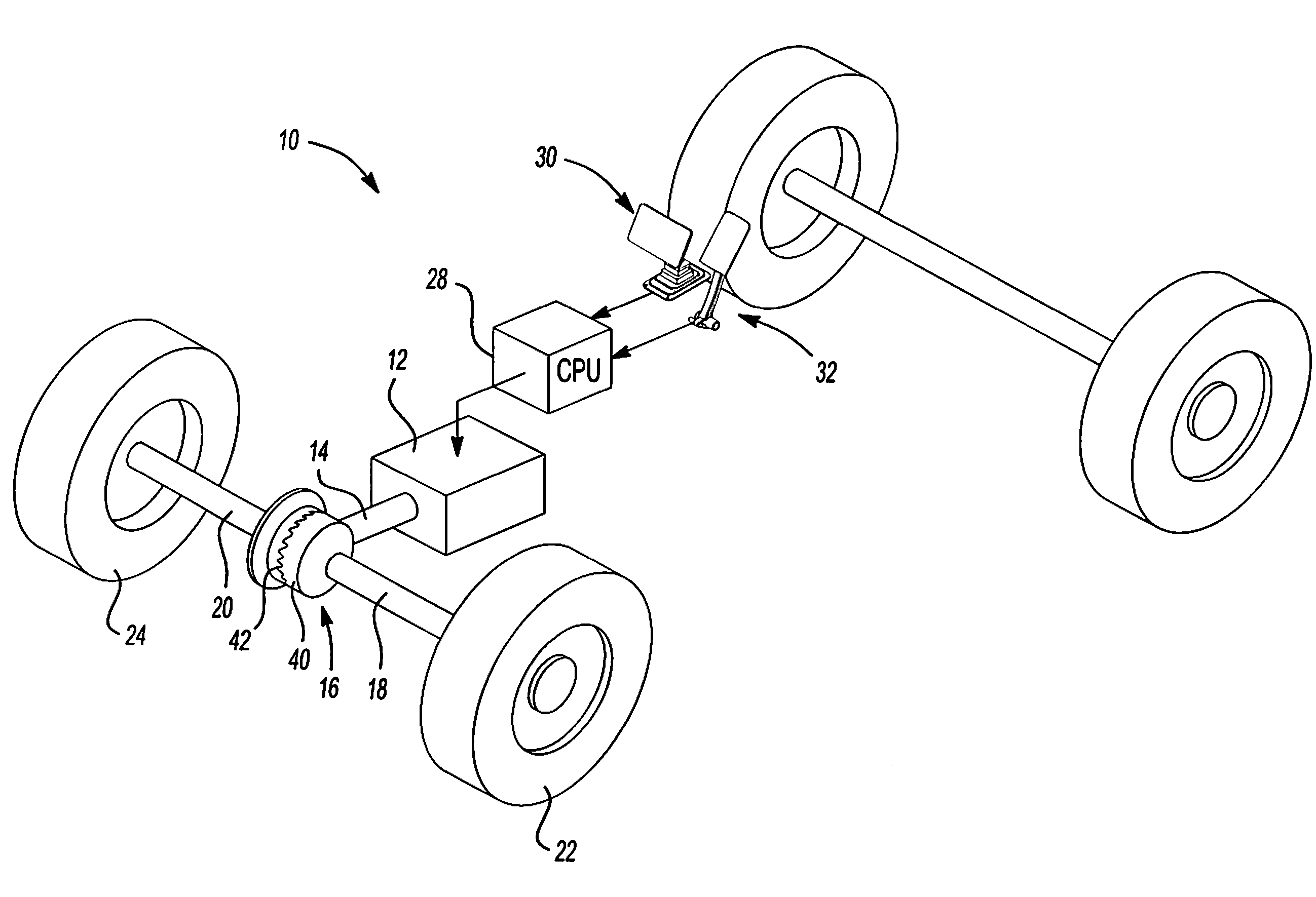
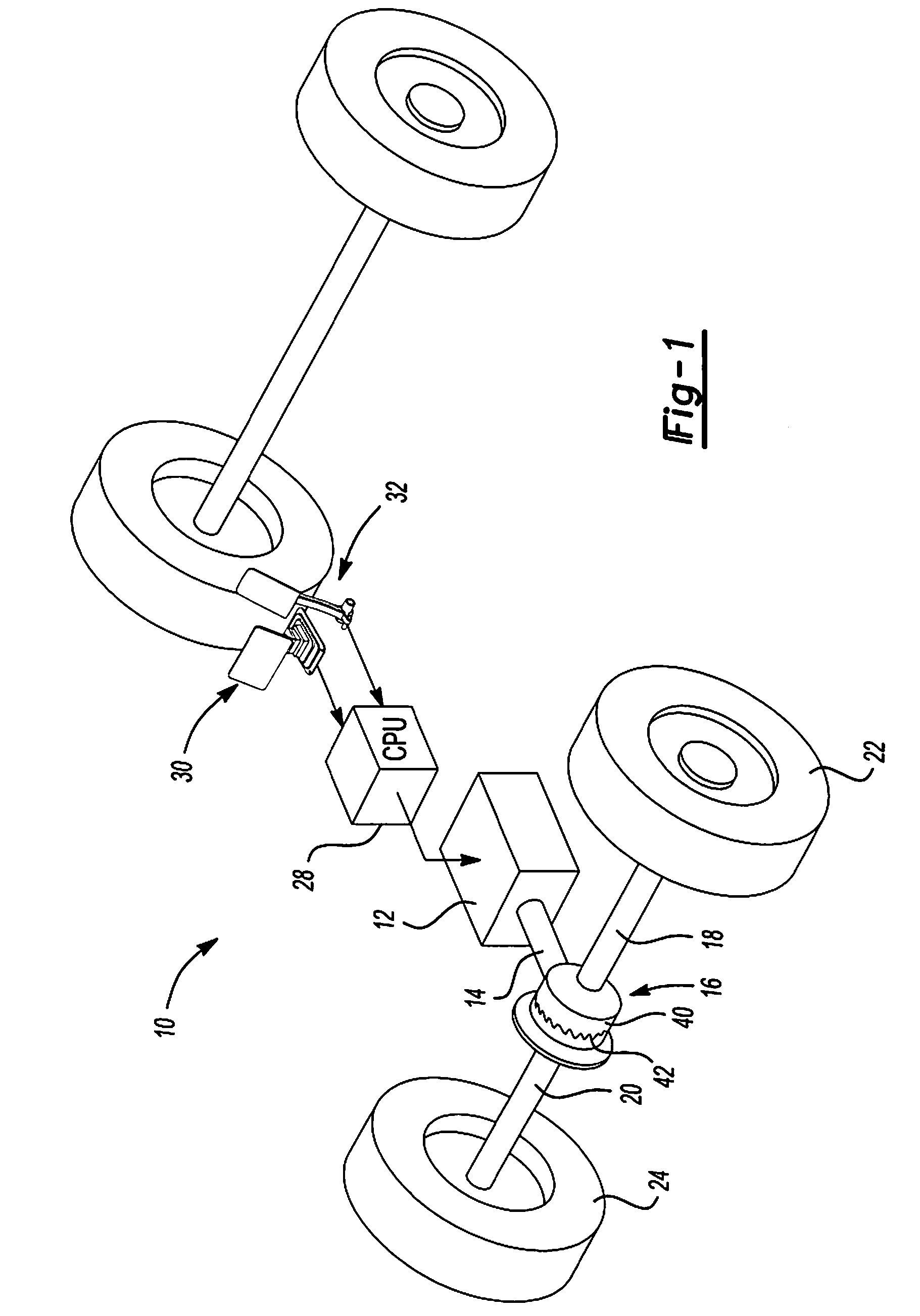
[0013]With reference to FIG. 1, an electric vehicle 10, such as a golf car or utility vehicle, is shown including an electric motor 12 including an output shaft 14 connected to a limited slip differential 16. The limited slip differential 16 includes first and second output axle shafts 18, 20 which are connected to the left and right rear drive wheels 22, 24, respectively.

[0014]A vehicle central processing unit 28 is provided for controlling operation of the motor 12 for providing driving torque as well as braking torque to the drive shaft 14. The central processing unit 28 receives signals from an accelerator pedal sensor 30 and a brake pedal sensor 32.

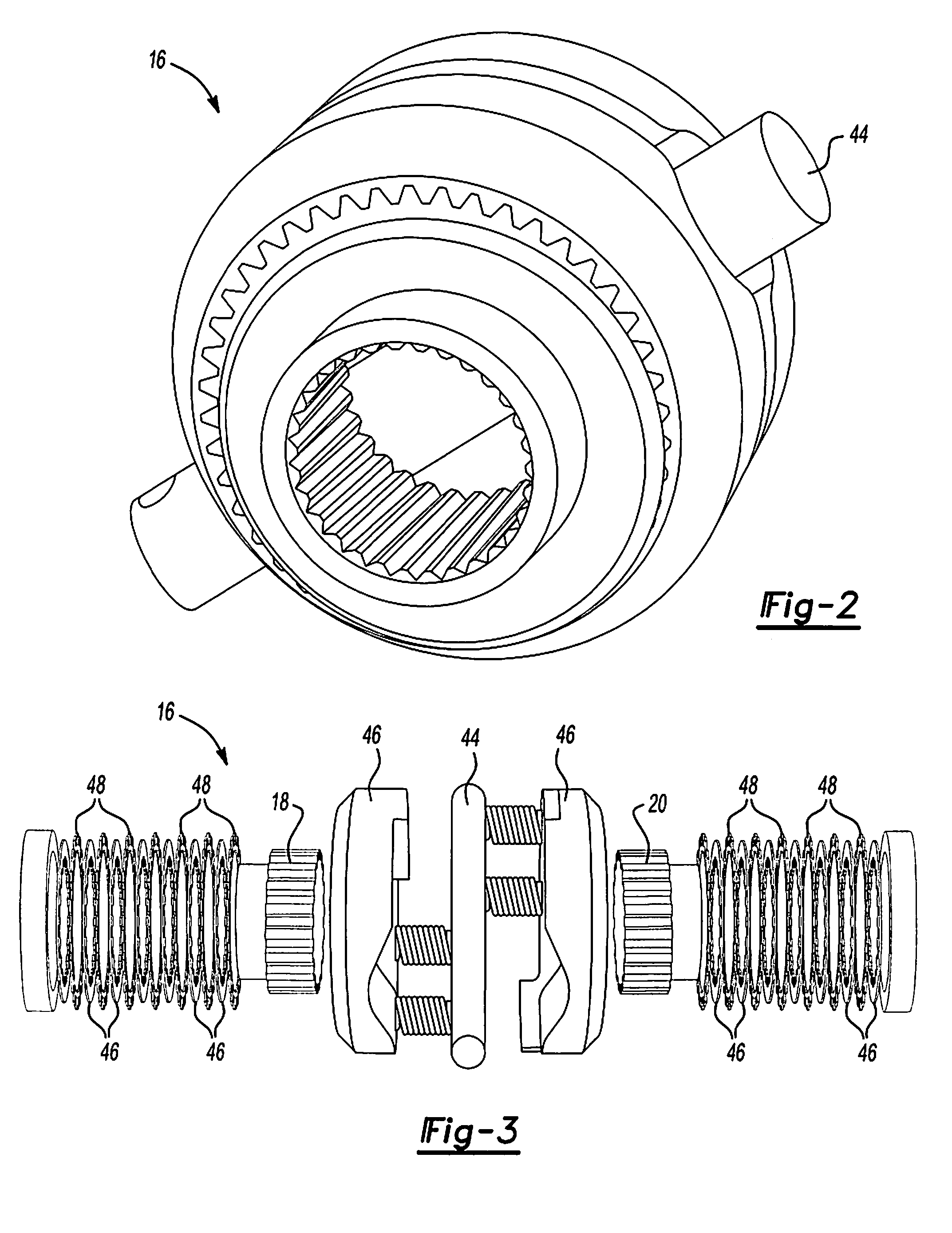
[0015]The limited slip differential 16 is provided to ensure ...


PUM


Abstract

An electric vehicle, such as a golf car or utility vehicle, is provided with an electric motor that provides dynamic braking for the vehicle. The vehicle drivetrain is provided with a limited slip differential in order to prevent the wheels from turning freely when traction is lost.

Description

FIELD[0001]The present disclosure relates to electric vehicles, and more particularly, to an electric vehicle having dynamic electric motor braking and a limited slip differential for preventing wheel slip during the dynamic braking mode.BACKGROUND AND SUMMARY[0002]The statements in this section merely provide background information related to the present disclosure and may not constitute prior art.[0003]Electric vehicles have grown more and more popular for use as golf cars and utility vehicles. Electric vehicles are relatively low maintenance and emit zero environmentally harmful emissions. In addition, electric vehicles are highly reliable.[0004]Although electric vehicles have proven to be very popular and efficient, the need to improve the vehicle's manufacture and assembly still exists. One area of recent development for electrical vehicles relates to the braking system. Examples of such inventions are disclosed in U.S. Pat. Nos. 6,457,568 and 6,686,719 which are commonly assig...

Claims


Application Information

Patent Timeline
Patent Type & Authority Applications(United States)
IPC IPC(8): B60K1/00A63B55/60F16H48/12
CPCB60K1/00B60K17/20B60L7/10B60L11/1881Y02T90/34B60Y2200/86F16H48/14F16H48/145B60L2200/22B60L58/30Y02T90/40F16H48/12
Inventor BELL, OLIVER A.CLARK, WARREN
Owner TEXTRON INC
Why Eureka
Try Eureka