Dot-matrix display refresh charging/discharging control method and system

a control method and display technology, applied in the field of dot-matrix display technology, can solve the problems of slow data refresh process and low power consumption, and achieve the effects of reducing power consumption in operation, and speeding up the data refresh process

Inactive Publication Date: 2009-04-30
NAT TAIWAN UNIV
View PDF7 Cites 4 Cited by
  • Summary
  • Abstract
  • Description
  • Claims
  • Application Information

AI Technical Summary

Benefits of technology

[0007]It is therefore an objective of this invention to provide a dot-matrix display data refresh charging / discharging control method and system which is capable of allowing faster data-refresh process and low power consumption in the operation of dot-matrix display devices.
[0008]The dot-matrix display data refresh charging / discharging control method and system according to the invention is characterized by the capability of prior to a data refresh action on each pixel, switching the pixel for connection to a voltage-neutralizing point for the purpose of neutralizing the current data voltage charge on the pixel to substantially approach zero voltage level; and subsequently during the data refresh action, charging a new data voltage into the pixel. This feature can effectively help speed up the data-refresh process with reduced power consumption, thus allowing the operation of the dot-matrix display device to have faster speed and low power consumption.

Problems solved by technology

However, due to the increase in the amount of pixels, one important issue in the design of these high-definition dot-matrix display devices is that the data-refresh process should be faster in order to maintain real-time display of video data.
Moreover, since portable electronic devices as notebook computers and intelligent mobile phones are typically powered by batteries which can supply electrical power for only a few hours, another important issue in the design of dot-matrix display devices is low power consumption.

Method used


Image

  • Dot-matrix display refresh charging/discharging control method and system
  • Dot-matrix display refresh charging/discharging control method and system
  • Dot-matrix display refresh charging/discharging control method and system

Examples


first preferred embodiment (fig.3)

First Preferred Embodiment (FIG. 3)

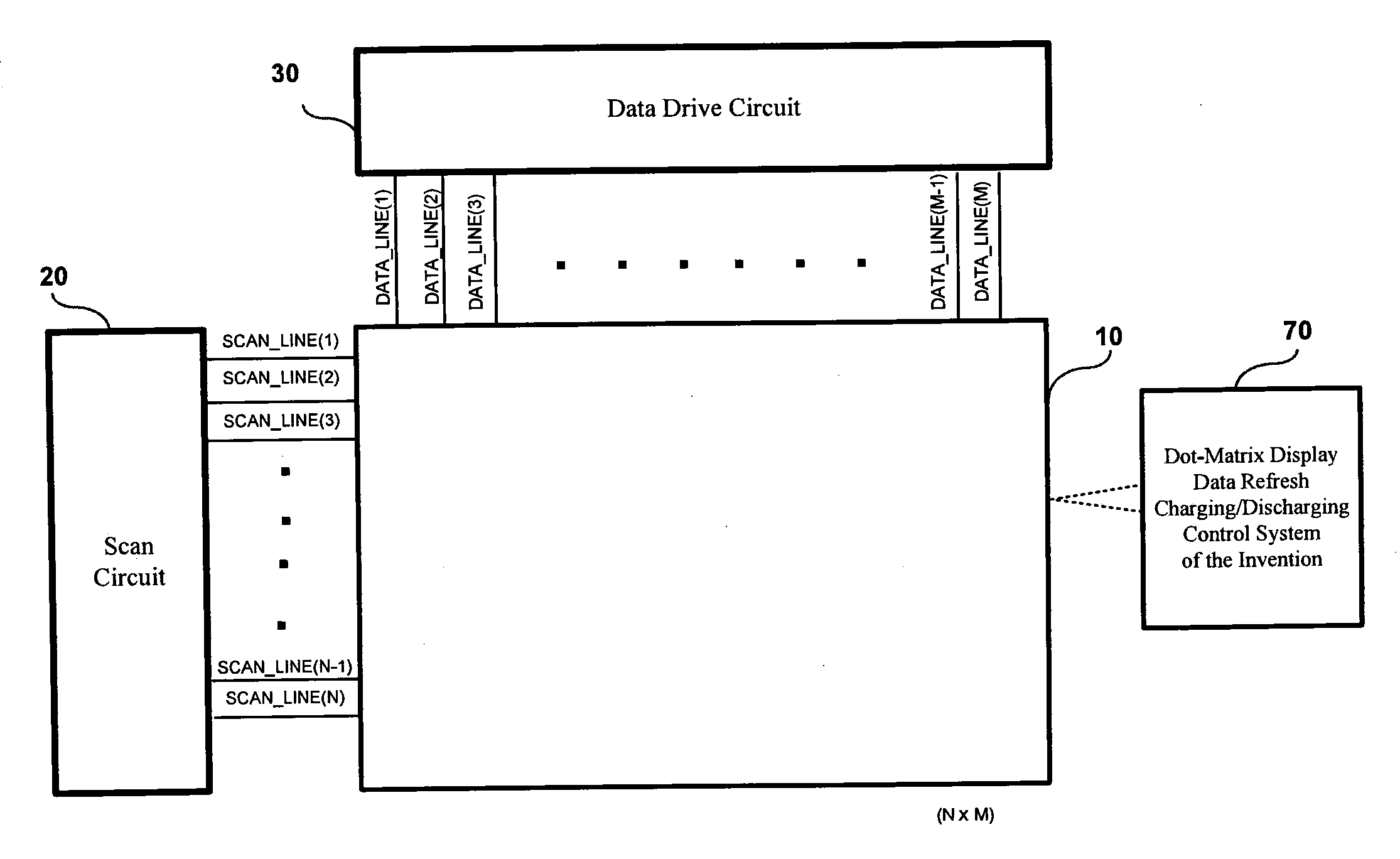
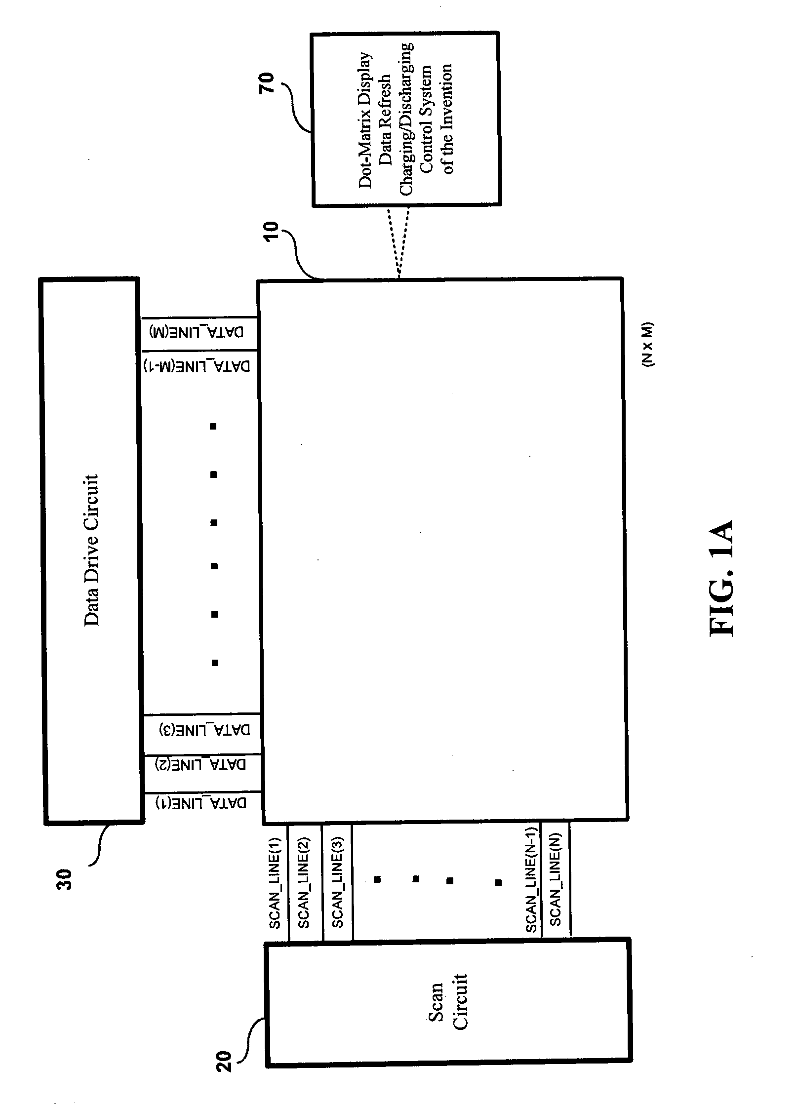
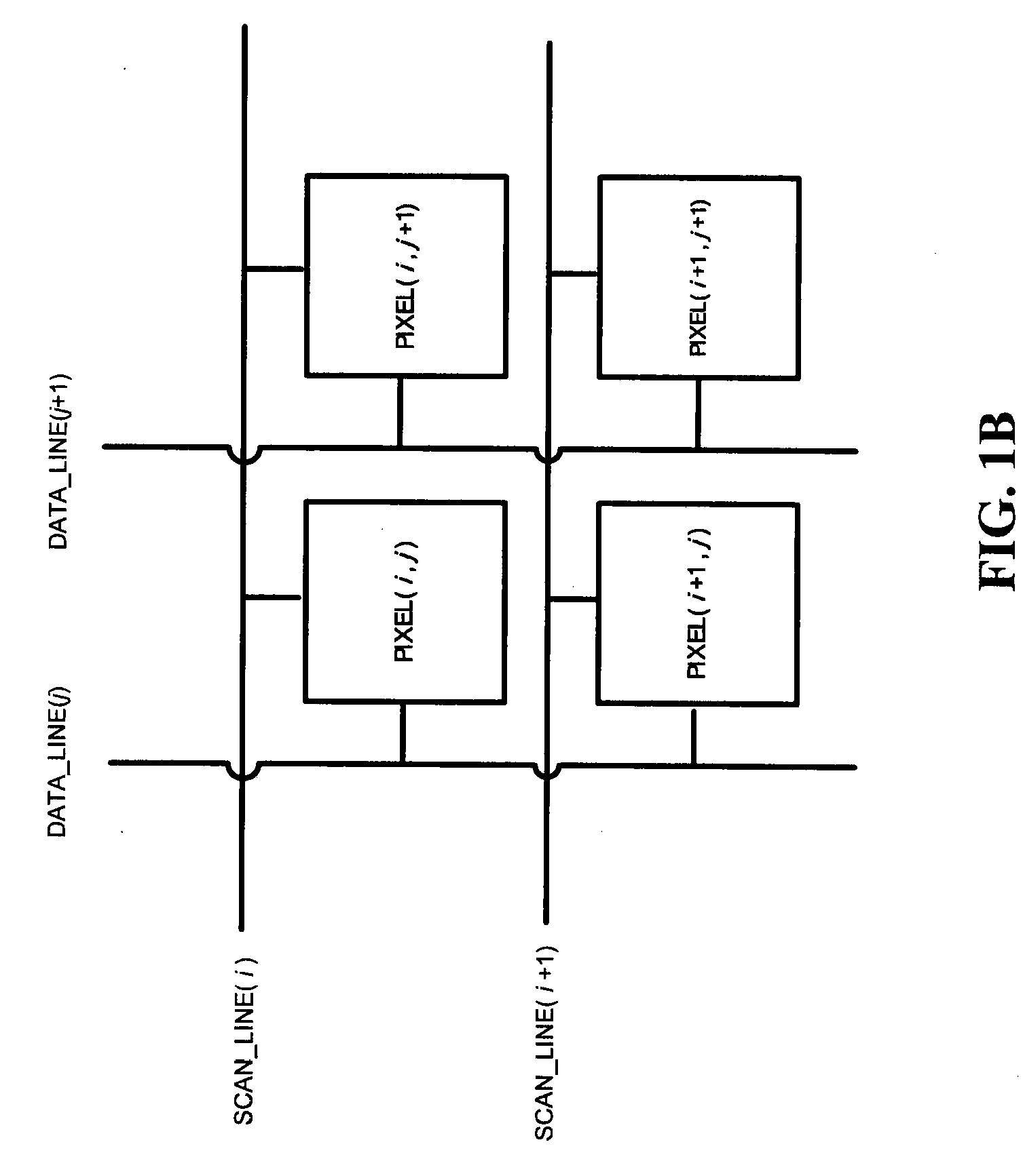
[0021]As shown in FIG. 3, the first preferred embodiment of the invention 100 is integrated to each pixel of the dot-matrix display device 10. In FIG. 3, only two vertically-adjacent pair of pixels PIXEL(i, j) and PIXEL(i+1, j) are demonstratively shown. Each pixel includes a capacitive circuit 40 having a liquid crystal capacitor CLC and storage capacitor Cs, whose two ends are respectively connected to a charge / discharge node NODE_C and a grounding line GND_LINE.

[0022]In circuit architecture, the first preferred embodiment of the invention 100 comprises: (A) a charging control switch 110; and (B) a charge-neutralizing control switch 120. The attributes and functions of these two constituent components 110, 120 are described in details in the following.

[0023]The charging control switch 110 is for example a TFT (thin-film transistor) switch, which is integrated to each pixel in such a manner that its gate is connected to one of the scan lines of th...

second preferred embodiment (fig.4)

Second Preferred Embodiment (FIG. 4)

[0028]The second preferred embodiment of the invention 200 is specifically designed for use with a dot-matrix display device 10 that utilizes the row-interleaved scheme shown in FIG. 2B or the dot-interleaved scheme shown in FIG. 2D for polarity inversion, where each vertically-adjacent pair of pixels are opposite in data voltage polarity.

[0029]As shown in FIG. 4, the second preferred embodiment of the invention 200 is integrated to each vertically-adjacent pair of pixels in the dot-matrix display device 10. In FIG. 4, only one pair of vertically-adjacent pixels PIXEL(i, j) and PIXEL(i+1, j) are demonstratively shown, where the upper PIXEL(i,j) includes a capacitive circuit 41, while the lower PIXEL(i+1, j) includes a capacitive circuit 42. The capacitive circuit 41 in the upper PIXEL(i, j) and the capacitive circuit 42 in the lower PIXEL(i+1, j) are each connected between a charge / discharge node NODE_C and a grounding point GND.

[0030]As shown in ...

third preferred embodiment (fig.5)

Third Preferred Embodiment (FIG. 5)

[0037]The third preferred embodiment of the invention 300 is specifically designed for use with a dot-matrix display device 10 that utilizes the column-interleaved scheme shown in FIG. 2C or the dot-interleaved scheme shown in FIG. 2D for polarity inversion, where each horizontally-adjacent pair of pixels are opposite in data voltage polarity.

[0038]The third preferred embodiment of the invention 300 differs from the second preferred embodiment of the invention 200 only in that the second preferred embodiment of the invention 200 is designed for charge neutralization between each vertically-adjacent pair of pixels, whereas the third preferred embodiment of the invention 300 is designed for charge neutralization between each horizontally-adjacent pair of pixels.

[0039]As shown in FIG. 5, the third preferred embodiment of the invention 300 is integrated to each horizontally-adjacent pair of pixels in the dot-matrix display device 10. In FIG. 5, only on...


PUM


Abstract

A dot-matrix display data refresh charging/discharging control method and system is proposed, which is designed for integration to a dot-matrix display device for providing a data refresh charging/discharging control mechanism on the dot-matrix display device. The proposed method and system is characterized by the capability of prior to a data refresh action on each pixel, switching the pixel for connection to a voltage-neutralizing point for the purpose of neutralizing the current data voltage charge on the pixel to substantially approach zero voltage level; and subsequently during the data refresh action, charging a new data voltage into the pixel. This feature allows the operation of the dot-matrix display device to have faster speed and low power consumption.

Description

BACKGROUND OF THE INVENTION[0001]1. Field of the Invention[0002]This invention relates to dot-matrix display technology, and more particularly, to a dot-matrix display data refresh charging / discharging control method and system which is designed for integration to a dot-matrix display device, such as a TFT-LCD (Thin Film Transistor Liquid Crystal Display) or an FSC (Field Sequential Color) device, for providing a data refresh charging / discharging control mechanism on the dot-matrix display device.[0003]2. Description of Related Art[0004]TFT-LCD (Thin Film Transistor Liquid Crystal Display) and FSC (Field Sequential Color) are two widely used dot-matrix display technologies on portable electronic devices such as notebook computers and intelligent mobile phones. In practice, a 15 TFT-LCD or FSC device is equipped with an N×M dot matrix which is an array of N rows and M columns of pixels, wherein each pixel is capable of displaying a particular color value in response to the charging o...

Claims


Application Information

Patent Timeline
Patent Type & Authority Applications(United States)
IPC IPC(8): G09G3/36
CPCG09G3/3614G09G2330/021G09G2310/0251G09G3/3659
Inventor LI, I-YINKIANG, JEAN-FU
Owner NAT TAIWAN UNIV
Why Eureka
Try Eureka