
Inspecting method and inspecting system of assembly

a technology of assembly and inspection method, which is applied in the direction of television system, material analysis using wave/particle radiation, instruments, etc., can solve the problems of time too long, inability to apply this in the inspection of mass-production products, and inability to identify the position in the propagating direction of x-rays, etc., to achieve high efficiency

Inactive Publication Date: 2009-04-30
HITACHI LTD
View PDF2 Cites 2 Cited by
  • Summary
  • Abstract
  • Description
  • Claims
  • Application Information

AI Technical Summary

Benefits of technology

[0011]According to the present invention, by taking the drawbacks mentioned above into the consideration thereof, an object thereof is to provide an inspecting method for inspecting the interior condition of and assembly, i.e., a target to be inspected, by obtaining the three-dimensional position relationships among the parts building up the assembly, in a short time. Further, another object thereof is to provide an inspecting system for the assembly with applying the inspecting method therein.
[0013]In this manner, since the brightness in the vicinity of boundaries of the part to be extracted can be calculated in each direction for photographing, thereby to determine the sensitivity of the photographing apparatus, as well as, to conduct the photographing in plural numbers of directions, therefore it is possible to provide the inspecting method of an assembly, for conducting an inspection of an interior condition, in short time, within the assembly, i.e., a target to be inspected.
[0015]According to the present invention mentioned above, since the three-dimensional position relationship can be known, in shot time, for each of the parts building up the assembly, therefore it is possible to provide an inspecting method of an assembly for conducting an inspection of success or failure of the assembly, with high efficiency.

Problems solved by technology

However, with the technology disclosed in the Patent Document 1, there is a problem, though it is possible to identify the position in the direction perpendicular to propagating direction of the X-rays irradiated, but it is impossible to identify the position in the propagating direction of the X-rays.
However, it takes the time too long, and therefore it is impossible to apply this in the inspection for the products of mass-production.

Method used


Image

  • Inspecting method and inspecting system of assembly
  • Inspecting method and inspecting system of assembly
  • Inspecting method and inspecting system of assembly

Examples


embodiment 1

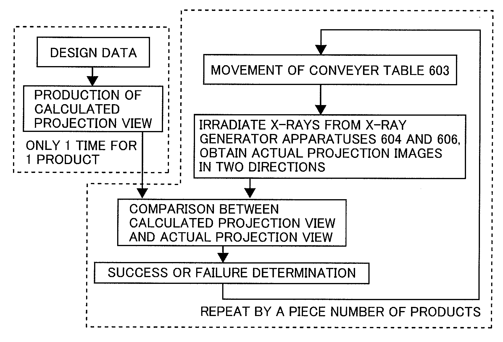
[0042]FIG. 6 is a view for showing the inspecting method for inspecting accuracy of assembling of the mass-produced assembly, according an embodiment 1. The assemblies 601 to be inspected are mounted on a conveyer table 603 at a predetermined distance therebetween. The X-ray emitting from an X-ray generator apparatus 604 passes through the assembly 601 in the horizontal direction, and reaches to a camera 605; thereby obtaining the projection image in the horizontal direction. Also, the X-ray emitting from an X-ray generator apparatus 606 passes through the assembly 601 in the vertical direction, and reaches to a camera 607; thereby obtaining the projection image in the vertical direction. However, in case where the conveyer table 603 prevents the X-ray projection image from being obtained, the material of the table may be changed or a hole may be provided. The projection image obtained in this manner is converted into an electric signal within the video processor portion 6, and it i...

embodiment 2

[0046]FIG. 9 attached is a view for showing an embodiment 2 of the present invention, and is a view for showing the condition of photographing with X-ray while cutting an inside a hole of cylinder-type with using a lathe. On a rotation shaft 901 of the lathe is attached a part 902, and the inside of the part 902 is cut by means of a bite (cutting tool) 903. At the positions where the hole and the bite 903 under machining can be photographed with X-ray are provided a set of the X-ray generator apparatus 904 and the camera 905 and a set of the X-ray generator apparatus 906 and the camera 907, respectively.

[0047]While adding the cutting depth of the part 902 at a predetermined rotation speed of the rotation shaft 901 and the position of the bite 903 as the design data, upon this design data is obtained the calculated projection view, in advance, and this is compared with the actual projection view, which is obtained through the photographing, thereby it is possible to obtain a differen...

embodiment 3

[0049]Explanation will be made on an embodiment 3 of the present invention. The embodiment 3 relates to an assembly built up with “N” pieces of parts, as the target to be inspected, and wherein the sizes and a mutual position relationship of each part are uses as the design data. From this design data are obtained the calculated projection views in two (2) directions, in advance. By comparing the actual projection views in two directions, which are obtained in the similar manner, with the calculated projection views, respectively, as was mentioned above, it is possible to obtain the differences between the actual position and the direction thereof and the design data, for each of “N” pieces of the parts, respectively.

[0050]By correcting the design data with this difference, and also producing a calculation mesh for use of a fluid-, heat- or structure-calculation with using this data, it is possible to conduct calculation simulation for reproducing an actual position relationship of ...


PUM


Abstract

An inspecting system of an assembly, for inspecting the assembly, by obtaining three-dimensional position relationship, in short time, for each of parts building up the assembly, comprises: a data editor / processor portion 2 for storing design data therein, and for producing / editing a calculated projection view; a brightness calculating portion 3 for calculating brightness in vicinity of boundaries, which are obtained when photographing the part to be extracted in plural numbers of directions, from the design data, for each direction; a sensitivity determining portion 4 for determining sensitivity of the photographing apparatus upon basis of the brightness, so that the projection image becomes clear in the vicinity of said boundaries; a photographing apparatus 5 for obtaining the projection images in the plural number of directions for the assembly conveyed; a video processor portion 6 for conducting video processing with converting the projection image into an electric signal, as an actual projection view; and a determination portion 8 for determining success or failure of the assembly, depending upon the part presented on the actual projection lies or not within a tolerable region of the part, which is presented by the calculated projection view.

Description

BACKGROUND OF THE INVENTION[0001]The present invention relates to an inspecting method of an assembly, which is constructed with a plural number of parts, and in particular, it relates to an inspecting method for conducting an inspection of the condition of assembling, with using a projection drawing calculated, which is obtained from design data, and a projection image of an interior condition of the assembly, which is obtained by photographing. Further, it relates to an inspecting system of applying this method therein.[0002]In general, an industrial product is an assembly made up with a plural number of parts thereof. For inspection of such the product, it is necessary to inspect the condition of assembling (for example, the degree of parallelism, and / or concentricity, etc.), in addition to an inspection of sizes for each part.[0003]Conventionally, for the purpose of inspecting the condition of interior assembling, an X-ray projection apparatus is well applied. Within the X-ray p...

Claims


Application Information

Patent Timeline
IPC IPC(8): H04N7/18
CPCG01N23/046G01N2223/419G01N2223/645G01N2223/643
Inventor SASAKI, ICHIROSADAOKA, NORIYUKIWATANABE, MASATOSHI
Owner HITACHI LTD
Features
  • Generate Ideas
  • Intellectual Property
  • Life Sciences
  • Materials
  • Tech Scout
  • Unparalleled Data Quality
  • Higher Quality Content
  • 60% Fewer Hallucinations
Learn More