Apparatus and method for measuring thermal diffusivity using the flash method

Inactive Publication Date: 2009-04-30
KOREA ADVANCED INST OF SCI & TECH
View PDF6 Cites 9 Cited by
  • Summary
  • Abstract
  • Description
  • Claims
  • Application Information

AI Technical Summary

Benefits of technology

[0018]Accordingly, the present invention has been made in view of the above problems occurring in the prior art, and it is the first object of the present invention to provide an apparatus and method, which can measure thermal diffusivity with precision and reproducibility by reflecting the thermal resistance value of a coated sample in the thickness of the sample.
[0019]It is the second object of the present invention to show a simple method of predicting the apparent thickness of this coated graphite.

Problems solved by technology

Especially, as new highly functional solid material and heat transfer medium are fast exploited with rapidly developing industries, establishment of a reliable and accurate measurement technique of the thermo-physical properties is highly demanding.
In the conventional thermal conductivity measurement technique in a steady state, the contact resistance between the test sample and the measuring tool causes non-negligible error, and the conventional measurement requires relatively long measurement time.
However, the additional graphite coating increases the thermal resistance of the sample.
This has become the most critical factor of an error occurring when measuring the thermal diffusivity.
However, according to this method, it is practically impossible to set an optimal thickness for every material because there is a need for the development of new materials and special functional materials with excellent thermal characteristics in these days.
However, the theories and experimental equations are not compatible with actually obtained experimental data.
This makes it difficult to apply the theories and experimental equations to actual material designs.

Method used


Image

  • Apparatus and method for measuring thermal diffusivity using the flash method
  • Apparatus and method for measuring thermal diffusivity using the flash method
  • Apparatus and method for measuring thermal diffusivity using the flash method

Examples


Embodiment Construction

[0040]The present invention will now be described in detail in connection with specific embodiments with reference to the accompanying drawings.

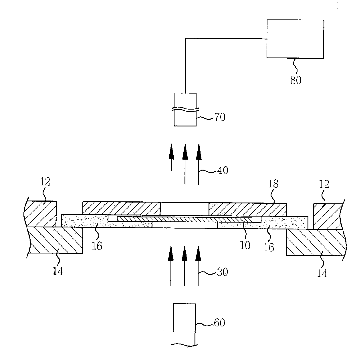
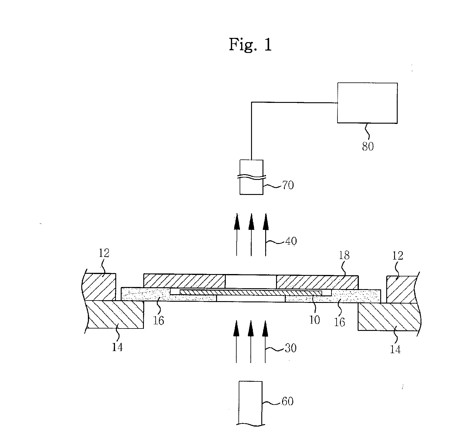
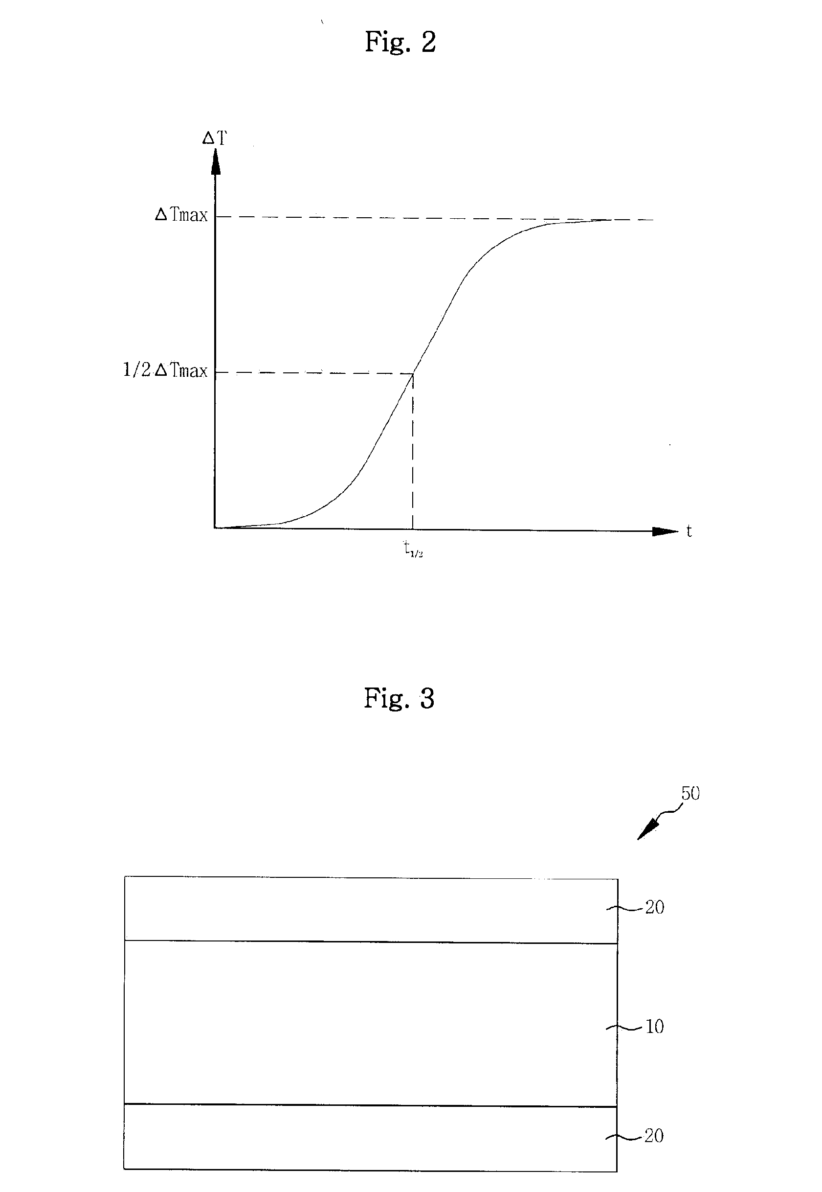
[0041]FIG. 3 is a sectional view showing the construction of a measurement sample 10 according to the present invention. As shown in FIG. 3, the front and rear surfaces of the measurement sample 10 are surrounded by a graphite layer 20. If the measurement sample 10 is formed as described above, the flash beam 30 incident on the front surface of the measurement sample 10, as shown in FIG. 1, is dissipated as the heat 40 at the rear surface of the measurement sample 10 as the temperature of the measurement sample 10 rises.

[0042]In the thermal diffusivity measurement device 100 according to the present invention, the measurement sample 10 is insulated by the sample holder 16, the first and second sample holder plates 12,14, and the sample cover 18 so that the heat dissipated from the measurement sample 10 is not emitted to other portions, as sh...


PUM


Abstract

The present invention relates to an apparatus and method for measuring thermal diffusivity using the flash method. The apparatus includes: a laser generator 60 for generating a flash beam 30; a measurement sample 10 having graphite layers 20 formed on front and rear surfaces thereof, through which the flash beam 30 passes; an infrared sensor 70 disposed at the rear of the measurement sample 10 for measuring a temperature and time at the rear surface of the measurement sample 10 from heat 40 dissipated from the measurement sample 10; and operation means 80 for performing an operation based on an output signal of the infrared sensor 70.

Description

BACKGROUND OF THE INVENTION[0001]1. Field of the Invention[0002]The present invention relates to an apparatus and method for measuring thermal diffusivity using the flash method, and more particularly, to an apparatus and method for measuring thermal diffusivity using the flash method, in which the thermal diffusivity of a sample can be measured accurately using the method of determining the resistance factor of coated graphite on the sample and measuring the apparent thickness of the coated sample.[0003]2. Background of the Related Art[0004]The accurate measurement of thermo-physical properties such as thermal diffusivity, specific heat and thermal conductivity is of prime importance in heat transfer analysis and application technologies in engineering. Especially, as new highly functional solid material and heat transfer medium are fast exploited with rapidly developing industries, establishment of a reliable and accurate measurement technique of the thermo-physical properties is ...

Claims


Application Information

Patent Timeline
IPC IPC(8): G01N25/20
CPCG01N25/18G01B11/06G01N21/35
Inventor KIM, SEOG KWANG
Owner KOREA ADVANCED INST OF SCI & TECH
Why Eureka
Try Eureka