Radio communications system designed for a low-power receiver

Active Publication Date: 2009-04-30
BIOTRONIK SE & CO KG
View PDF32 Cites 76 Cited by
  • Summary
  • Abstract
  • Description
  • Claims
  • Application Information

AI Technical Summary

Benefits of technology

[0021]Another advantage of the invention is that because the low-power receiver's architecture is considerably simpler than a traditional super-heterodyne receiver, it uses fewer components, and hence the receiver can be made considerably smaller in size.
[0022]According to the invention, the intermediate frequency signal, or baseband signal, is received from a transmitter within a pair of high frequency carriers because the two high frequency carriers already contain the intermediate frequency, or baseband signal, in the superposition of two high frequency carriers. The intermediate frequency, or baseband signal, can also be seen as the beat frequency resulting from the mixing or heterodyning of the two high frequency carriers.
[0023]Since both high frequency carriers are received by the antenna, the high frequency carriers are superimposed within the antenna. The received second high frequency carrier signal replaces the locally generated local oscillator signal in a typical super-heterodyne receiver, and the nonlinear device in the invention replaces the mixer section used in a traditional super-heterodyne receiver.
[0024]In one embodiment of the invention, the low power receiver is adapted to convert the high frequency carriers to an intermediate frequency signal, and then demodulate the intermediate frequency signal with a demodulator so as to convert the IF signal into a baseband signal. The conversion of the high frequency carriers to the intermediate frequency signal is done simply by receiving th

Problems solved by technology

Since all electronic devices consume electrical energy, medical implants with batteries that are not readily accessible, or easily replaced, must operate with minimal power consumption.
In any event, the radio telemetry circuitry in the implant consumes battery power, and the hence impacts the longevity of the implant.
As a consequence, the device's radio receiver wi

Method used


Image

  • Radio communications system designed for a low-power receiver
  • Radio communications system designed for a low-power receiver
  • Radio communications system designed for a low-power receiver

Examples


Embodiment Construction

[0107]The following description is of the best mode presently contemplated for carrying out the invention. This description is not to be taken in a limiting sense, but is made merely for the purpose of describing the general principles of the invention. The scope of the invention should be determined with reference to the claims.

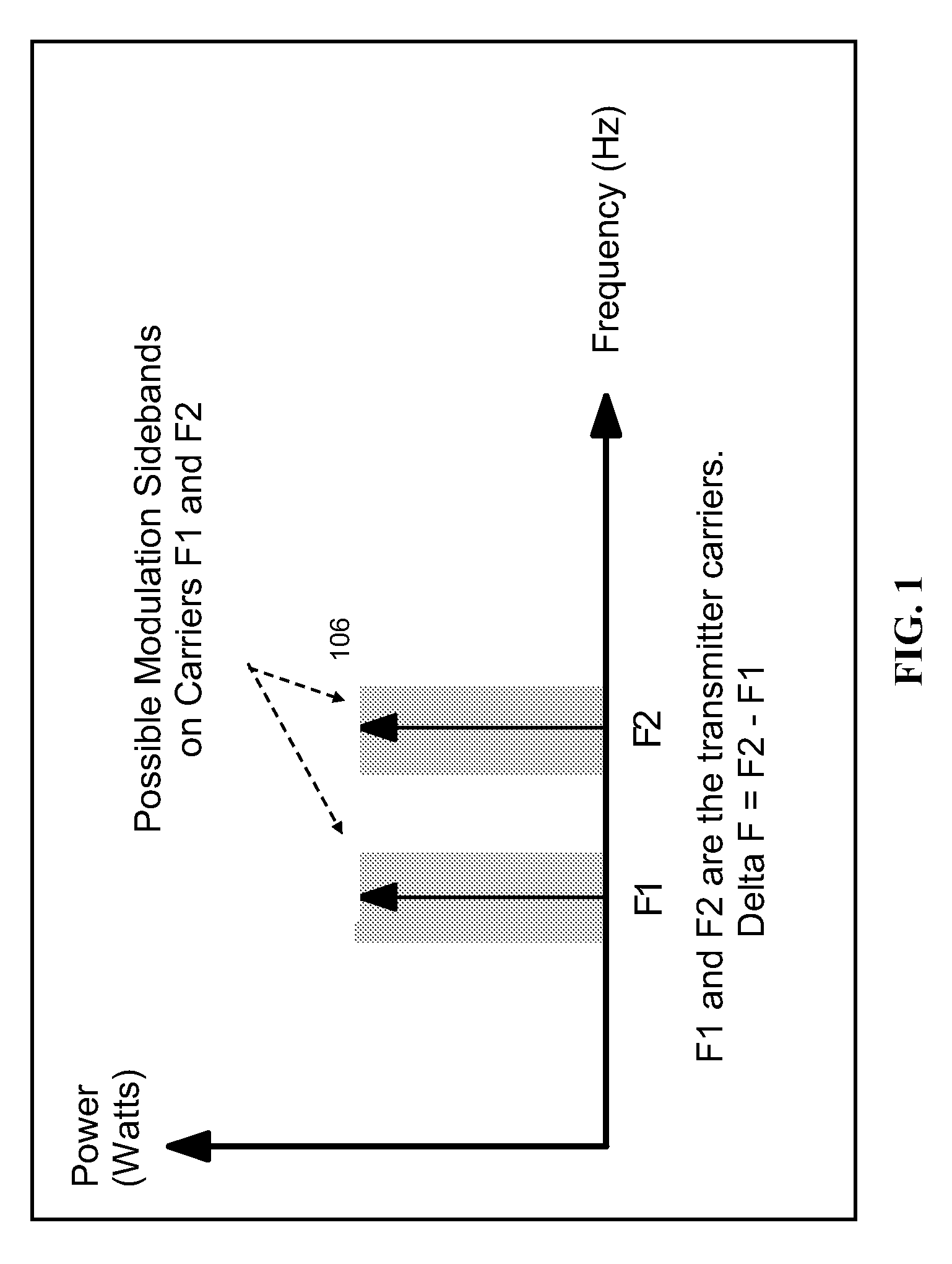
[0108]FIG. 1 shows, schematically, the frequency spectrum of a transmitter with two high frequency carriers at different frequencies F1 and F2. The high frequency carriers may not have modulation sidebands (i.e. they may be only CW carriers), or one, or both carriers may have modulation sidebands 106. None, one, or all high frequency carriers may be modulated. In the following the high frequency carriers may be referred to simply by carriers. The carriers of two frequencies mix with each other and produce new signals at the frequency F1+F2 and at delta F=|F2−F1|. Delta F can be used for a low power receiver design, because although F1 and F2 may be very high...


PUM


Abstract

The invention relates to methods by which radio signals can be transmitted to, and received by, a radio receiver such that the receiver consumes very little power from a battery or energy source. The invention also relates to methods by which radio signals, modulated with data information, can be produced by a transmitter that consumes very little power. The invention is applicable not only to medical implants, but any application requiring a radio receiver to operate with very low power consumption.

Description

[0001]This application is a continuation in part of U.S. patent application Ser. No. 11 / 877,821, filed 24 Oct. 2007, the specification of which is hereby incorporated herein by reference.BACKGROUND OF THE INVENTION[0002]1. Field of the Invention[0003]The invention relates to a low power radio frequency receiver, a matching transmitter, a communication method for a low power receiver, and an electromagnetic signal.[0004]2. Description of the Related Art[0005]State-of-the-art battery powered medical implants must not only provide the prescribed therapy, but they must also be as small as possible, extremely reliable, and have a long service life. For example, the service life of cardiac pacemakers and implantable cardioverter defibrillators (ICDs) is expected to be seven years or more. Since all electronic devices consume electrical energy, medical implants with batteries that are not readily accessible, or easily replaced, must operate with minimal power consumption. Batteries in medi...

Claims


Application Information

Patent Timeline
IPC IPC(8): H04B1/40H04B1/16H04B1/04H04B1/69H04L27/04H04L27/00
CPCH04B1/40H04B1/24
Inventor SUTTON, BRIAN P.NELSON, JIMSTADNIK, PAULROLISON, GARYBERTHELSDORF, RICHARD
Owner BIOTRONIK SE & CO KG
Why Eureka
Try Eureka