Methods and apparatuses for improving power extraction from solar cells

a technology of solar cells and solar energy, applied in electrical apparatus, semiconductor/solid-state device manufacturing, semiconductor devices, etc., can solve the problems of reducing the series resistance of metal grid, affecting the conversion efficiency, and significantly reducing the solar conversion efficiency and less power extraction, so as to minimize the ohmic resistance associated, maximize solar energy conversion efficiency, and reduce the effect of energy loss

Inactive Publication Date: 2009-05-07
E CUBE ENERGY TECH CO LTD
View PDF9 Cites 36 Cited by
  • Summary
  • Abstract
  • Description
  • Claims
  • Application Information

AI Technical Summary

Benefits of technology

[0012]In this invention, methods and apparatuses based on the consideration of minimizing ohmic resistances associated with solar cells installed in modules are provided for the purposes of reducing the energy losses stemmed from electrical resistance and maximizing solar energy conversion efficiency. A number of schemes are designed to take advantage of the geometrical and mechanical configurations of solar cells with both polarities of metal contacts on the back surface (back-contact solar cells) to make better electrical contacts and connections so as to achieve maximum solar energy conversion efficiency and better power extraction.

Problems solved by technology

Among them, energy losses arising from ohmic resistance of the metal grid of the back contact of solar cells and of the electrical connections between the cells installed on a solar module may cause significant decrease in solar conversion efficiency and less power extraction than it should be.
The resistance of the metal grids that are in direct contact with the surfaces of solar cells may affect conversion efficiency drastically.
It also reduces the series resistance of metal grid because the contacts can be very broad covering almost entire back surface.
Since the resistance of metal fingers is proportional to L / D, there is still a relatively large resistance that may cause considerably energy loss because the connection bus for both electrical polarities of a back-contact solar cell is at the opposite edges.
Energy loss is inevitable when current flows through those narrow and thin fingers across almost entire length of the cell.
However, it is rather difficult to realize all these on the cell level due to various constrains associated with materials properties and related to production process and manufacturing cost issues.

Method used


Image

  • Methods and apparatuses for improving power extraction from solar cells
  • Methods and apparatuses for improving power extraction from solar cells
  • Methods and apparatuses for improving power extraction from solar cells

Examples


Embodiment Construction

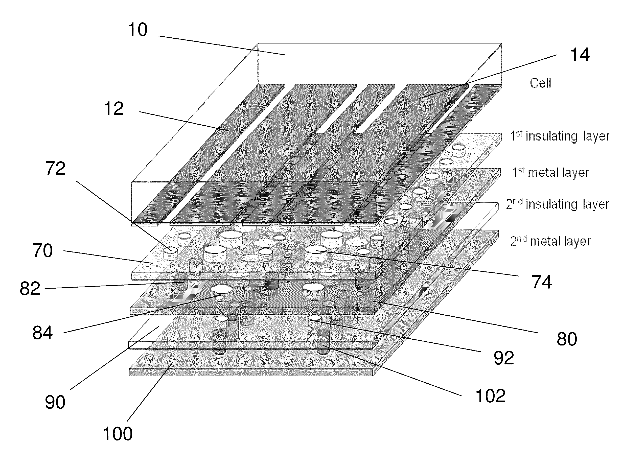
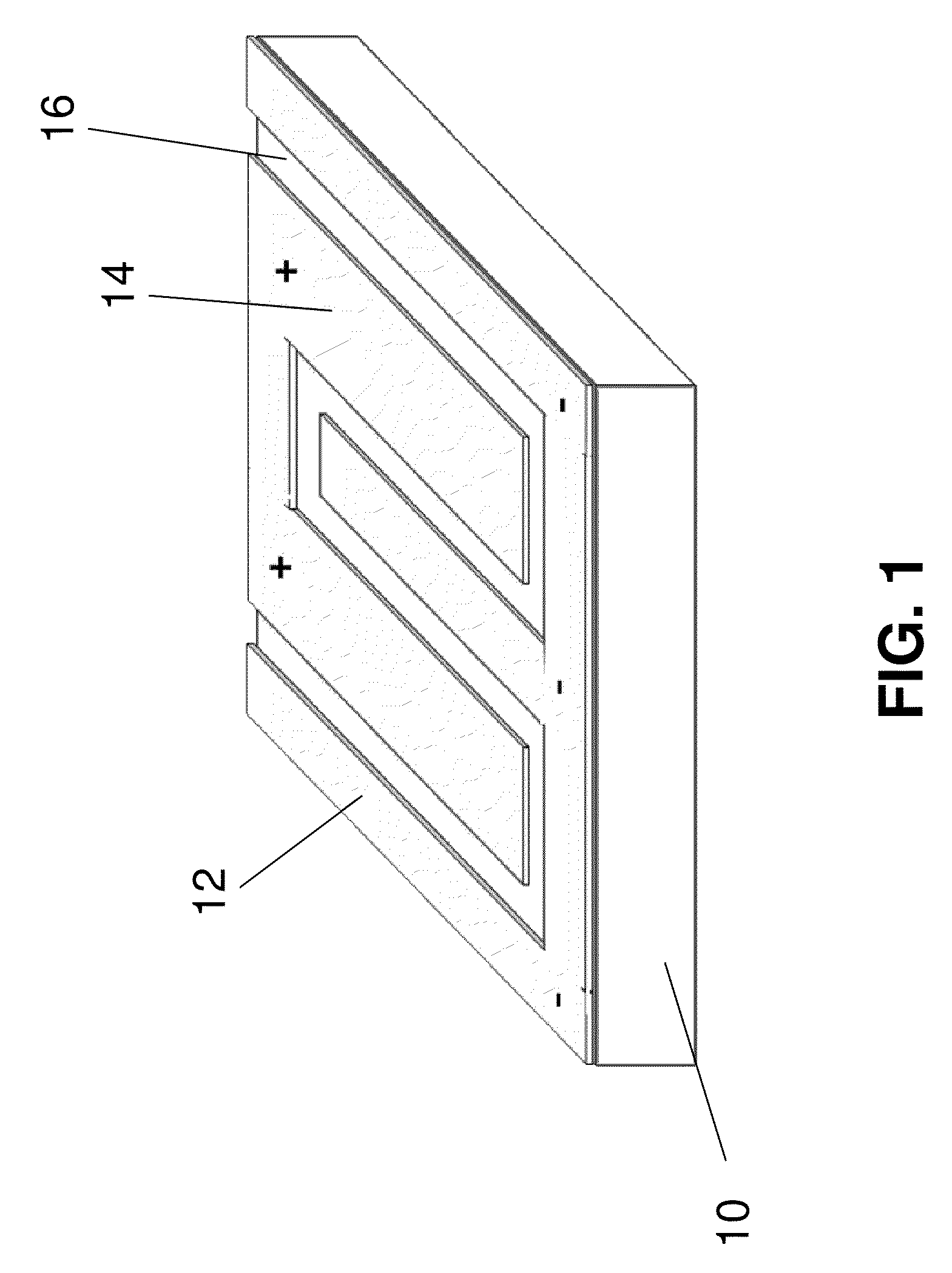
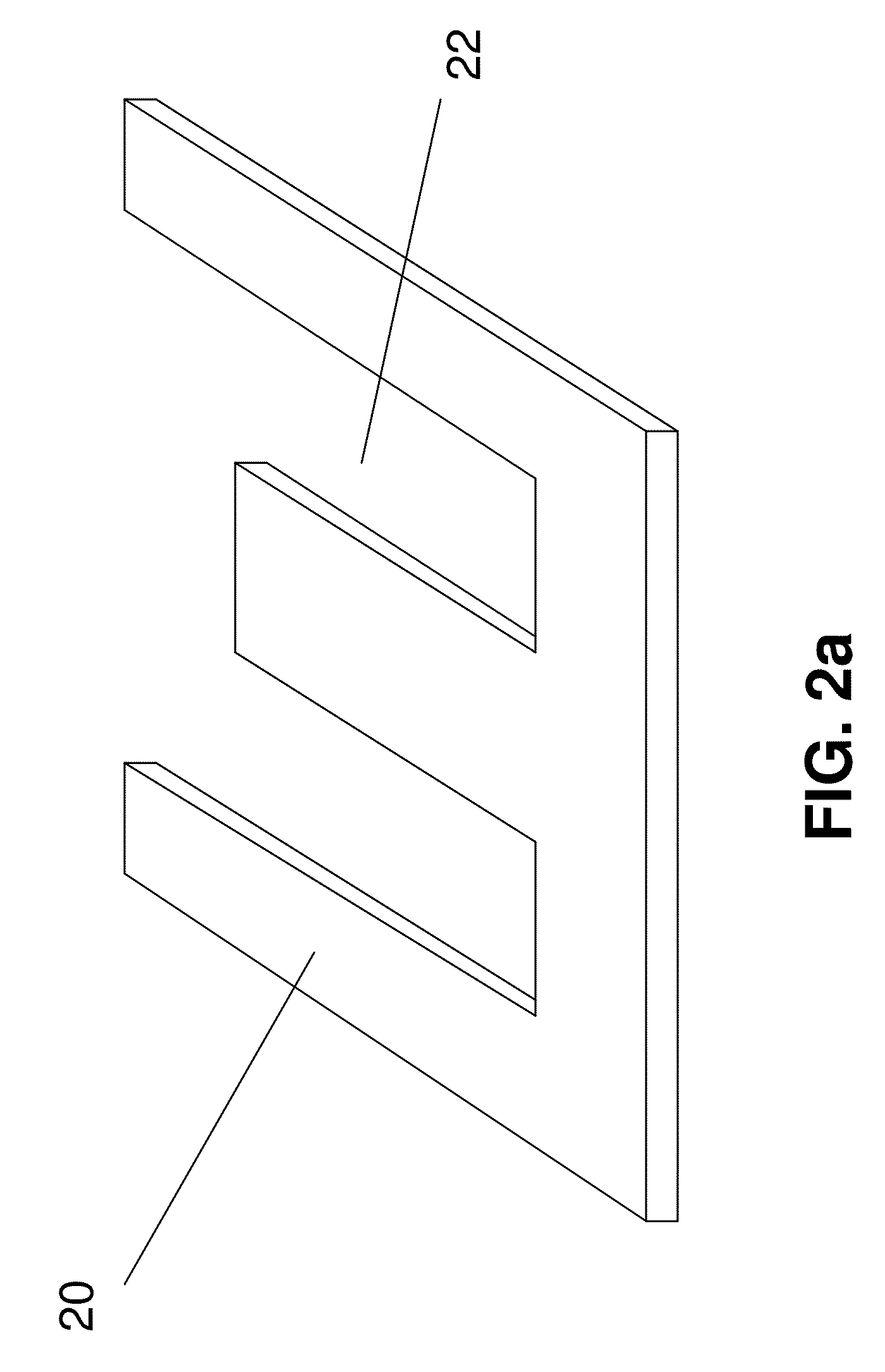
[0024]The foregoing background and summary, as well as the following detailed description of the drawings, will be better understood when read in conjunction with the appended drawings. For the purpose of illustrating the invention, there is shown in the drawings embodiments which are presently preferred. It should be understood, however, that the invention is not limited to the precise arrangements and instrumentalities shown. Throughout the drawings, like reference numerals refer to like elements. The terms “front” and “back” are used to distinguish between the different surfaces of an element. The use of the terms does not mean that the “front” surface always comes before the “back” surface. Either position is considered to be within the scope of the invention.

[0025]Disclosed herein are schemes designed to utilize the geometrical configuration and mechanical structure of back contact solar cells to minimize energy losses resulted from ohmic resistances related to solar cells used...


PUM


Abstract

The field of the invention relates to minimization of resistive loss of solar panels in order to achieve maximum solar energy conversion efficiency, extracting more electricity power from available solar irradiance. Schemes are designed to take advantage of the geometrical and mechanical configurations of back contact solar cells to make better electrical contacts and connections so as to achieve maximum solar energy conversion efficiency and better power extraction.

Description

[0001]This application claims the priority of U.S. Provisional Patent Application No. 60 / 934,871, filed Jun. 18, 2007.BACKGROUND OF THE INVENTION[0002]1. Field of the Invention[0003]Embodiments of the present invention are directed to the field of photovoltaics (PV) technology that converts solar energy directly into electrical energy. The field of the invention is specifically directed to minimization of resistive loss of solar panels in order to achieve maximum solar energy conversion efficiency, extracting more electrical power from available solar irradiance.[0004]2. Description of the Related Art[0005]Practical solar cells have a number of limits including reflection, contact shadowing, series resistance, incomplete collection of photogenerated carriers, absorption in the inactive window layers, nonradiative recombination, etc. that can affect energy conversion efficiency. Among them, energy losses arising from ohmic resistance of the metal grid of the back contact of solar cel...

Claims


Application Information

Patent Timeline
Patent Type & Authority Applications(United States)
IPC IPC(8): H01L31/00H01L21/00
CPCY02E10/50H01L31/0516H01L31/02245
Inventor SHAN, WEICHEN, ZITONG
Owner E CUBE ENERGY TECH CO LTD
Why Eureka
Try Eureka