
Magnetizer utilizing rotated assemblies of permanent magnets

Inactive Publication Date: 2013-12-05
OBRIEN ROBERT NEVILLE
View PDF7 Cites 8 Cited by
  • Summary
  • Abstract
  • Description
  • Claims
  • Application Information

AI Technical Summary

Benefits of technology

This patent describes a method for improving the efficiency of electrochemical reactors by reducing the time needed to reach a given output and minimizing the energy input required. The method does this by reducing the resistance and heating in the electrolyte solution. The text also mentions that the method can be applied to any electrochemical reactor that uses stirring, and that the use of a magnetic circuit can further improve the efficiency of the reactor. The technical effects of the method include faster processing times, reduced energy input, and improved performance.

Problems solved by technology

Joule heating, however, is undesirable in cells to which the present invention is intended to apply.

Method used


Image

  • Magnetizer utilizing rotated assemblies of permanent magnets
  • Magnetizer utilizing rotated assemblies of permanent magnets
  • Magnetizer utilizing rotated assemblies of permanent magnets

Examples


Embodiment Construction

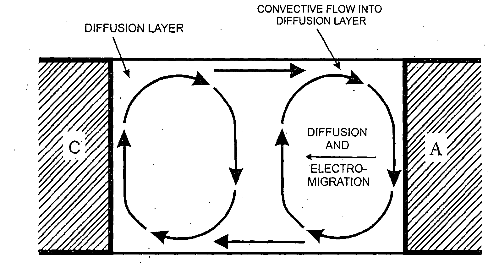
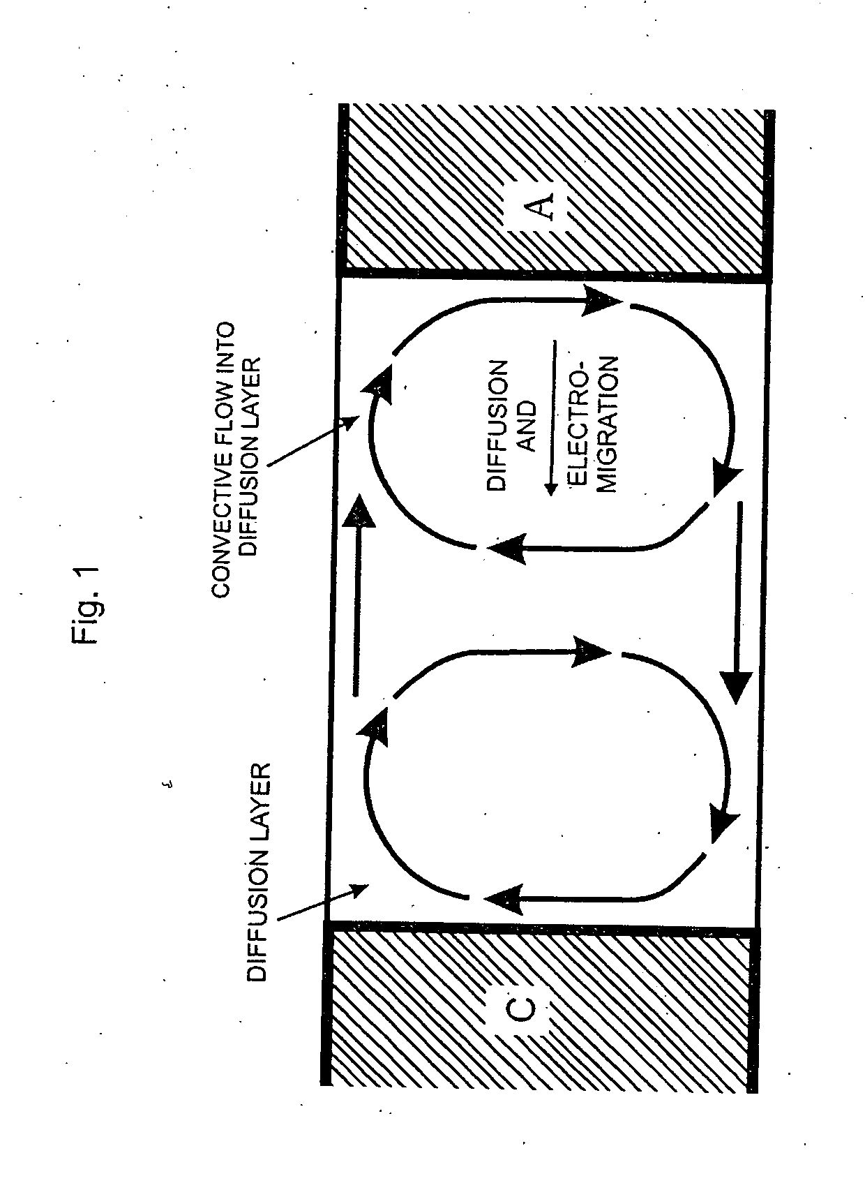
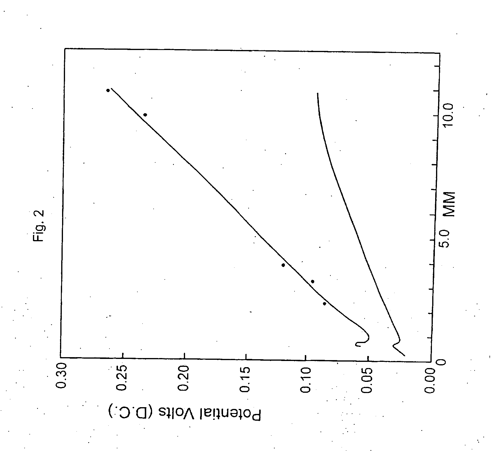
[0046]A particularly and especially advantageous feature of the present invention is that it enables instituting, for any suitably arranged and constituted (magnetically enhanced) electrochemical cell, essentially the same voltage-lowering effect that was discovered in the course of academic investigations by R. N. O'Brien and K. S. V. Santhanam, reported by them in the following publications: “Electrochemical Hydrodynamics in a Magnetic Field with Laser Interferometry”, Electrochimica Acta, 32, 1679 (1987); and Electrochemical Hydrodynamics in Magnetic Fields with Laser Interferometry; Influence of Paramagnetic Ions”, J. Appl. Electrochem., v. 20 (1990). To afford artisans easy access to the early interferometric evidence of this important voltage-lowering effect, the graphs, from these publications FIGS. 4 and 5 should be perused and for practical-sized cells the rest of the figures to FIG. 9. No drawing has been made to show an external source of magnetic field as used in FIGS. 1...


PUM


Abstract

Magnetohydrodynamics (MHD) has applications in all electrochemical processes and in a few that are not totally electrochemical in nature. By magnetizing the electrodes or the current collectors through the electrodes so that the vertical, closely and appropriately spaced magnetized electrodes produce a uniform, low magnetic field between them, north pole to south pole, the Lorentz force enhances the natural or forced convection where it is the greatest, very near the electrodes. Because the main internal resistance of an electrochemical process resides in the electrolyte, increasing the speed of transport of charged particles from one electrode to the other greatly reduces this internal resistance. Other treatments such as adding an indifferent paramagnetic ion, an indifferent free radical, completing the magnetic circuit, using a spacer which does not obscure the electrode surface, further reduce the internal resistance, lowering the wasted energy which usually appears as heat in the electrolyte.

Description

FIELD OF THE INVENTION[0001]In general, this invention relates to performing current-driven current-producing electrochemical processes, limited to those for which it is logical to expect advantages from mobilizing the bulk of electrolyte solution between positive and negative electrodes, maintaining a constant state of macroscopic-scale liquid motion to improve mass transport during performance of an electrochemical reaction to produce an intended chemical product.[0002]In operation of current-driven electrochemical processing reactors of the mobilized or, ie., “stirred-electrolyte” types to which the present invention is meant to apply, it is universally understood to be desirable to attain as large a ratio as possible, of electrochemically made product to the amount of direct current electricity fed to cell electrodes over a definite period of time. Whatever the particular scheme of current-driven process may be, its much desired efficiency tends to be hindered by factors such as...

Claims


Application Information

Patent Timeline
IPC IPC(8): H01F13/00
CPCH01F13/003C25B15/00C25C7/04C25C7/06H01M4/04H01M10/345H01M2004/021Y02E60/10
Inventor O'BRIEN, ROBERT NEVILLE
Owner OBRIEN ROBERT NEVILLE
Learn More