Flexible pipe

a flexible pipe technology, applied in the field of flexible pipes, can solve the problems of reducing the flexibility insufficient safety measures, and enlarge the outer diameter of the flexible pipe,

Active Publication Date: 2009-05-07
HITACHI METALS LTD
View PDF16 Cites 32 Cited by
  • Summary
  • Abstract
  • Description
  • Claims
  • Application Information

AI Technical Summary

Benefits of technology

[0008]Accordingly, an object of the present invention is to provide a flexible pipe sufficiently protecting a corrugated metal pipe from induced lightning.
[0009]Another object of the present invention is to provide a flexible pipe comprising a conductive layer near a corrugated metal pipe, the conductive layer being closer to a ground potential than the corrugated metal pipe, so that lightening current generated in the flexible pipe by spark discharge due to large potential difference in the building can escape to the ground through this conductive layer, to prevent direct discharge and damage to the corrugated metal pipe.DISCLOSURE OF THE INVENTION
[0010]The flexible pipe according to one embodiment of the present invention comprises a resin layer and a conductive coating layer in this order from below on an outer surface of a corrugated metal pipe for flowing a fluid. Even with spark discharge occurring in the flexible pipe by induced lightning, this coating structure protects the corrugated metal pipe from having apertures, thereby preventing gas leak, etc.
[0013]The flexible pipe according to another embodiment of the present invention comprises a first resin layer, a conductive metal layer, and a second resin layer in this order from below on an outer surface of a corrugated metal pipe for flowing a fluid. Even with spark discharge occurring in the flexible pipe by induced lightning, this coating structure protects the corrugated metal pipe from having apertures, thereby preventing gas leak, etc.
[0016]The flexible pipe according to a further embodiment of the present invention comprises a corrugated metal pipe for flowing a fluid, a first insulating resin layer covering the entire outer surface of the corrugated metal pipe, pluralities of metal tapes longitudinally extending on the outer surface of the first insulating resin layer, and a second insulating resin layer covering the entire outer surface of the first insulating resin layer via the metal tape, the first and second insulating resin layers being easily peelable. With this structure, (a) lightening current is completely prevented from flowing through the corrugated metal pipe, and (b) the metal tape can be easily removed by peeling the second insulating resin layer.

Problems solved by technology

It has been found, however, that the formation of a conductive coating layer on the outer surface of a corrugated metal pipe as described in JP2002-174374A, JP2003-083483A and JP2003-083482A, and the winding of a self-fusible insulating tape as a shielding metal layer around the metal pipe as described in JP2002-310381A and JP2002-315170A are insufficient as safety measures to the induced lightning.
It is not easy to completely insulate the corrugated metal pipe, and attempts to secure insulation to the spark discharge make the insulating layer too thick, resulting in providing the flexible pipe with reduced flexibility, disadvantageous for piping.
It also enlarges the outer diameter of the flexible pipe, thereby needing large joints to be connected.

Method used


Image

  • Flexible pipe
  • Flexible pipe
  • Flexible pipe

Examples


first embodiment

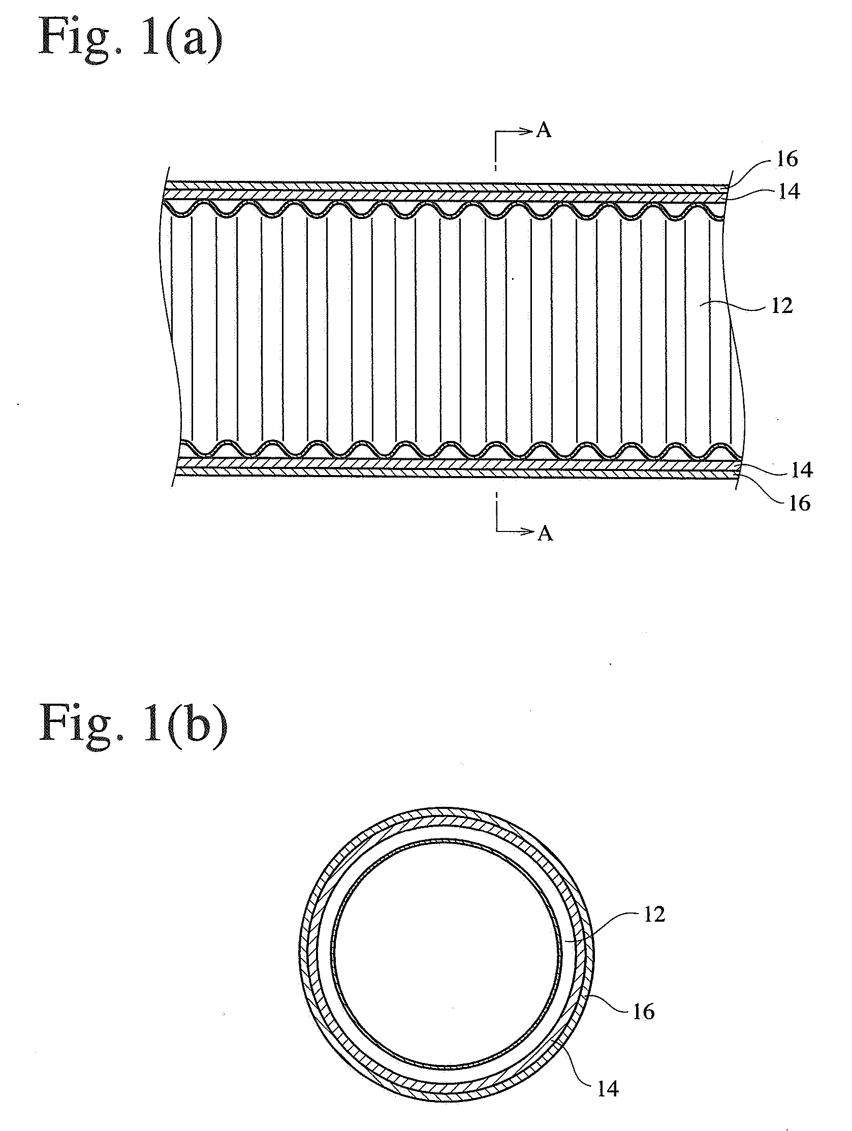
[0030]FIGS. 1(a) and 1(b) show a flexible pipe according to the first embodiment of the present invention. The flexible pipe in the first embodiment comprises a resin layer 14 and a conductive coating layer 16 formed in this order on the entire outer surface of a corrugated metal pipe 12 having the same structure as that of the conventional corrugated metal pipe 2 shown in FIG. 7. The resin layer 14 is preferably a high-insulation, soft vinyl chloride resin layer having a thickness of about 0.5-1 mm, but it may be a conductive resin layer. The conductive resin layer may be obtained by blending highly flexible resins such as rubbers or vinyl chloride resins, etc. with fine conductor particles such as metal powder, carbon black, carbon fibers, etc. The resin layer 14 may be formed by an extrusion lamination method.

[0031]The conductive coating layer 16 is preferably made of high-conductivity metals such as copper, aluminum, etc., but it may be formed by a conductive paint having slight...

second embodiment

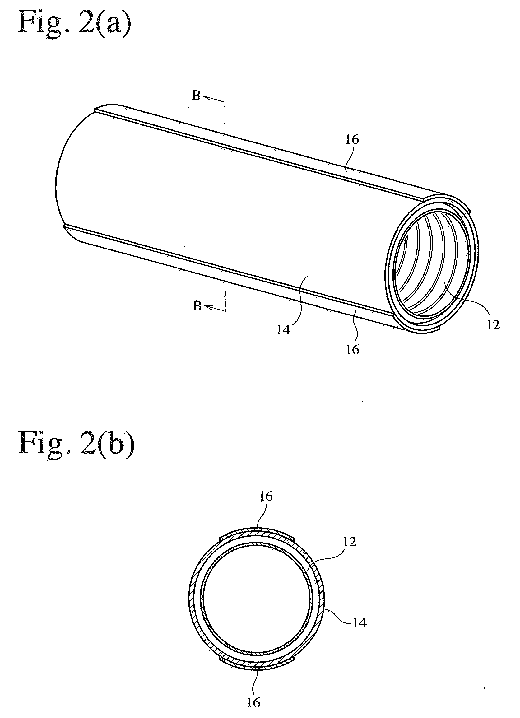
[0034]The outermost conductive coating layer 16 need not cover the entire outer surface of the corrugated metal pipe 12, but may be partially formed on the resin layer 14. In examples shown in FIGS. 2 and 3, the conductive coating layer 16 is constituted by pluralities of longitudinally extending conductive tapes, which partially cover the resin layer 14 formed on the entire outer surface. The conductive coating layer 16 is constituted by two conductive tapes disposed at a circumferential interval of 180° in the example shown in FIG. 2, and by four conductive tapes disposed at a circumferential interval of 90° in the example shown in FIG. 3. The conductive tape is preferably a metal tape of about 10 mm in width and about 0.02-0.1 mm in thickness, such as a metal foil tape of copper, etc., for instance, when the corrugated metal pipe 12 has a diameter of about 15-28 mm.

[0035]The use of pluralities of metal tapes is to provide the flexible pipe with improved reliability in induced lig...

third embodiment

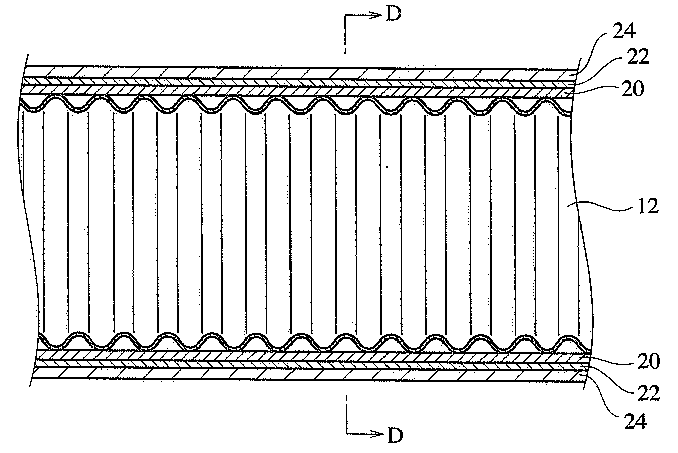
[0038]FIGS. 4-6 show a flexible pipe according to the third embodiment of the present invention. This flexible pipe has a three-layer coating comprising a first resin layer 20, a conductive metal layer 22 and a second resin layer 24 on the entire outer surface of a corrugated metal pipe 12. The first and second resin layers 20, 24 may be conductive or insulating. The second resin layer 24 protects the metal layer 22 from corrosion, thereby preventing the metal layer 22 from peeling by an external force (for instance, bending force) during installation. The conductive resin layer may be the same as described above. The insulating resin layer may be a high-insulation, soft vinyl chloride layer having a thickness of about 0.5-1 mm like as in the first embodiment. The metal layer 22 is grounded. Both first and second resin layers 20, 24 may be formed by an extrusion lamination method.

[0039]Accordingly, the coating layer may have a structure of (a) an insulating resin layer, a metal laye...


PUM


Abstract

The formation of a resin layer, a metal layer and an insulating resin layer on an outer surface of a corrugated metal pipe for flowing a fluid provides a flexible pipe, whose corrugated metal pipe does not suffer from having apertures even with spark discharge by induced lightning.

Description

FIELD OF THE INVENTION[0001]The present invention relates to a flexible pipe for fluids such as gas, water, etc. which is installed in the walls or under the floors of buildings, etc., particularly to a flexible pipe having a safety measure to induced lightning caused by lightening, etc.BACKGROUND OF THE INVENTION[0002]Recently, flexible pipes are widely used in piping in buildings, etc. for fluids such as gas, water, etc. As shown in FIG. 7, a flexible pipe generally used is produced by corrugating a hoop sheet of stainless steel having a thickness of about 0.2-0.5 mm, and forming a soft vinyl chloride resin layer 4 having a thickness of about 0.5-1 mm on the outer surface of the resultant bendable corrugated metal pipe 2.[0003]When lightening hits near a building, large current of lightening intrudes into the building through conductors such as the ground, the steel frames of the building, electric wires, etc. This phenomenon is called “induced lightning.” Although the corrugated ...

Claims


Application Information

Patent Timeline
Patent Type & Authority Applications(United States)
IPC IPC(8): F16L11/15F16L11/00F16L9/06F16L9/14F16L11/11F16L11/127F16L11/20H02G3/04
CPCF16L11/15H02G3/0468F16L11/20
Inventor MOHRI, MASAHIROFUJIYOSHI, MINORUSATOH, FUMITAKAHAMAGUCHI, TAMAKIMINAMI, TOMOYUKI
Owner HITACHI METALS LTD
Why Eureka
Try Eureka